Rockabillyrat
SlIgHtLy StUpId.
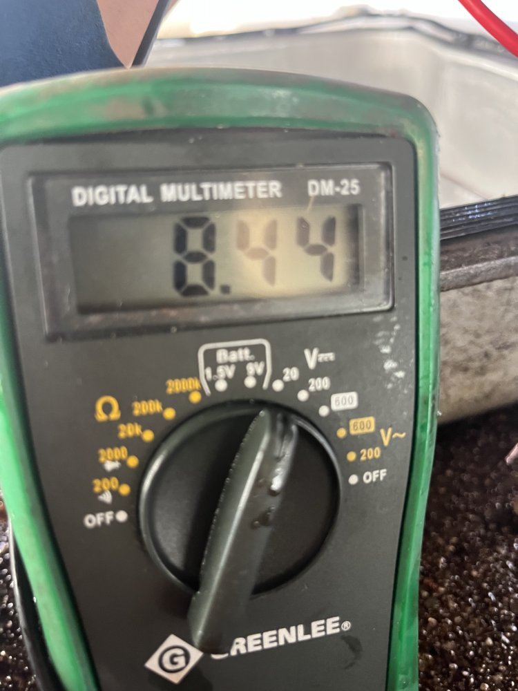
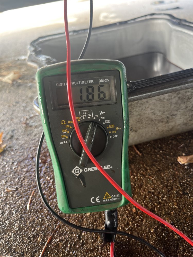
You guys are way overcomplicating this. I would plug everything back in but the RED TCM connector. Next put your meter in DC AMP and connect one end to the battery +. Probe Pin 22 and add a ground to pin 23, record the amperage reading of PCS A. Do the same thing for pin 24 and add ground to pin 25. Record the amperage reading for PCS B. Both PCS are identical other than one is NO and the other is NC. They both should OHM out to 5.5. So the amperage reading for both will be nearly identical. If you get two different amperage readings then you have a wiring, connection, or solenoid issue. If both read the same them you more than likely have a TCM issue.
You need to command the TCM to turn on the PCS to test for the 7v in the flow chart. Your not going to get anywhere testing it without commanding it on.
If I had this in the shop this is exactly what I would do. I've been at this for over 20 years...
Edit. also Unplug PCS A with everything else plugged back in. Turn the key on and set you meter to OHM, You should have O.L on both wires with the other end of the meter on B+ and B- That will test for a short to ground or power on the circuit.
Last edited: