• Welcome to The Truck Stop! We see you haven't REGISTERED yet.

    Your truck knowledge is missing!
    • Registration is FREE , all we need is your birthday and email. (We don't share ANY data with ANYONE)
    • We have tons of knowledge here for your diesel truck!
    • Post your own topics and reply to existing threads to help others out!
    • NO ADS! The site is fully functional and ad free!
    CLICK HERE TO REGISTER!

    Problems registering? Click here to contact us!

    Already registered, but need a PASSWORD RESET? CLICK HERE TO RESET YOUR PASSWORD!

Bye-bye Gov-Lock, Hello Tru Trac, plus gear swap and brakes

Yeah open cover. Just a small pump for some engine oil out a couple flex hoses like used for metal band saw to run oil over the bearings and gear face. It wouldn’t have to run high speed before noise showed up. It was a vairable speed controlled motor, so they could test to a range. Having no load on the system means it isn’t going to burn up right away.

He originally built it to break in a real wear pattern on new set ups to eliminate friction for more free go-fast, so his controller had volt & amp gauges on for reading load. You can guess from that part how I met him- haha. For breaking in the gears he would install cover and oil. It ran a couple hours, open and inspect, then run overnight. Next day open and adjust as needed. He would do the set up on his machine and do some fine fitment work for a FEE. Notice the word fee is not small there...
You wouldn’t believe how much of the gears can be chopped away for less contact area when you only want one race season out of a set of gears. Frees up alot of drag.
 
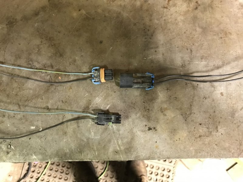
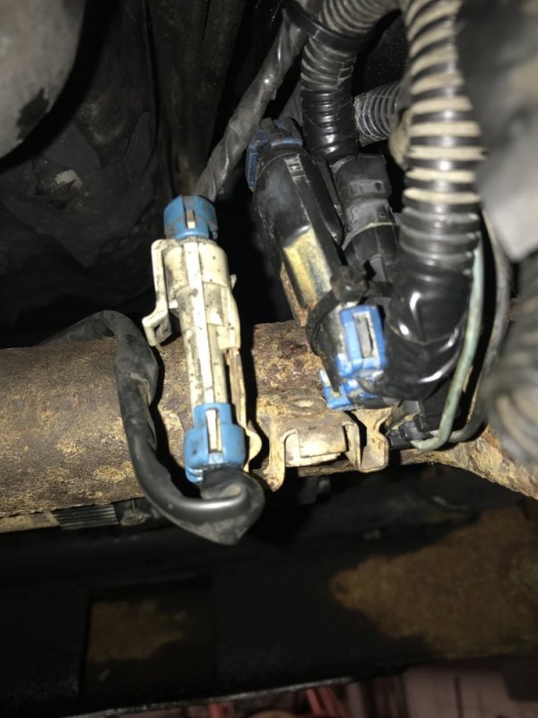
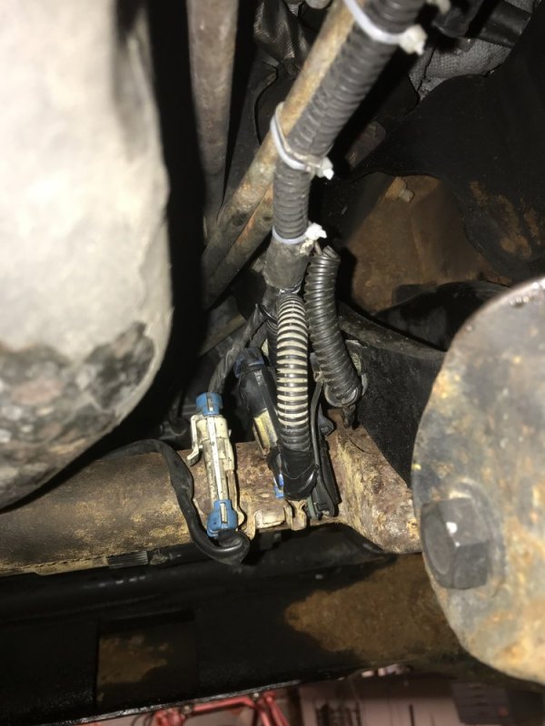
I ran to the junkyard today for a couple things today. One thing I grabbed was the 4wd actuator plug off a 97 truck. I grabbed both the male and female ends just in case. Good thing I did - when I got it unwrapped I found that both wires were black. Luckily the truck end had color coding. I laid that next to the harness that came with the front diff and that gave me my layout.
B2C79D82-00AE-4CCE-AF08-1910EABFC2DF.jpeg

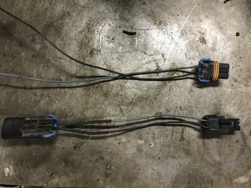
I cut, soldered and then added heat shrink.

324DB311-C0A0-4E19-A215-9D6A1E189369.jpeg

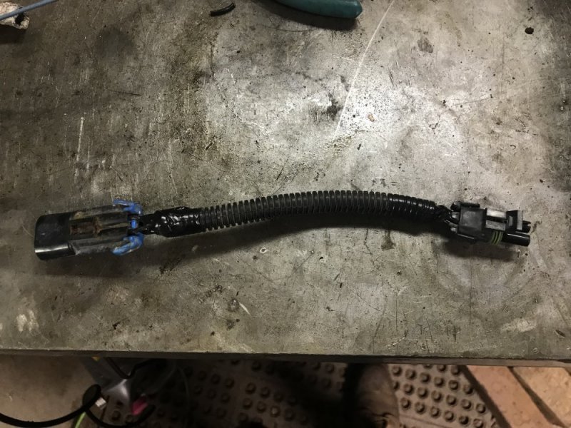
Then I wrapped it in wire conduit.

9F65B122-04CB-405B-8A84-17D454DFE134.jpeg

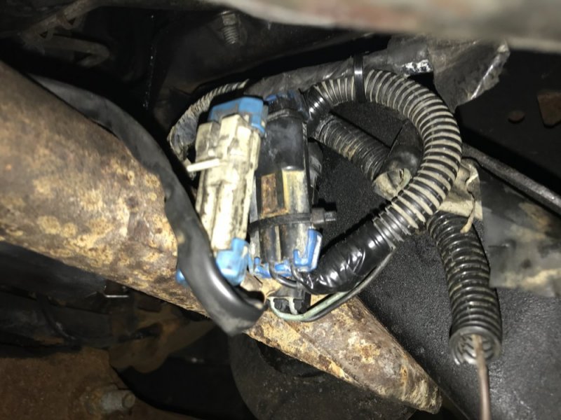
Then it was a simple matter of plug-n-play on the truck.

A79469DA-BF3B-49DA-A89E-179029D8319B.jpeg E63B789A-5FE8-4748-B250-F17300214782.jpeg

Now I just need to run the brown wire to a switched source.


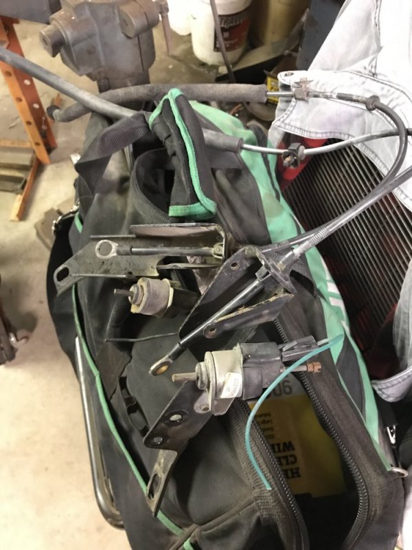
Off topic: while at the junkyard I found 2 mechanical throttle trucks so I snagged the cables and brackets for just-in-case in the future.....

7E4F41A2-1C0E-4BAA-A039-594A5E040670.jpeg
 
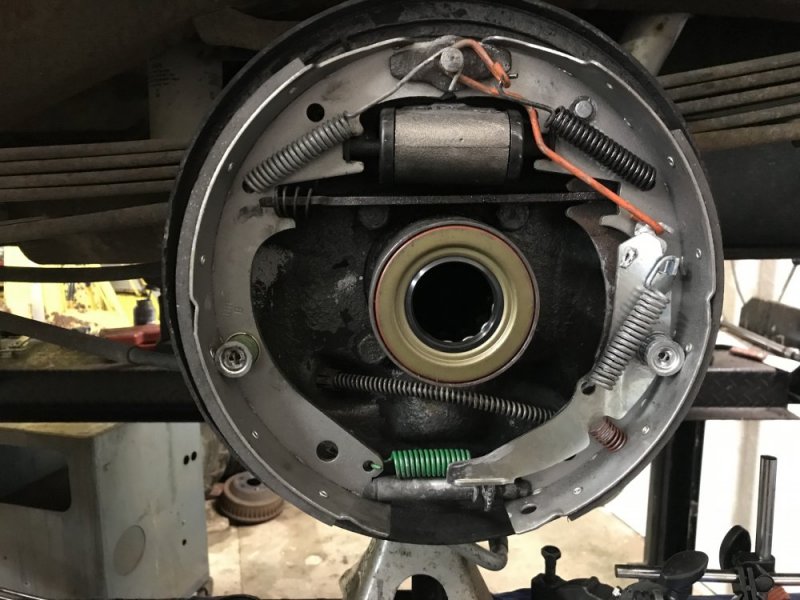
Started on the brakes today. I was able to get the rears done with the exception of the drum install and adjustment since I don’t have axles in at the moment. New axle seals too. I did get the 1-3/16” DRW wheel cylinders to see how that acts.

3AC03C8A-2747-4F8F-B4A1-858E79EB2964.jpeg

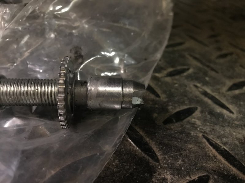
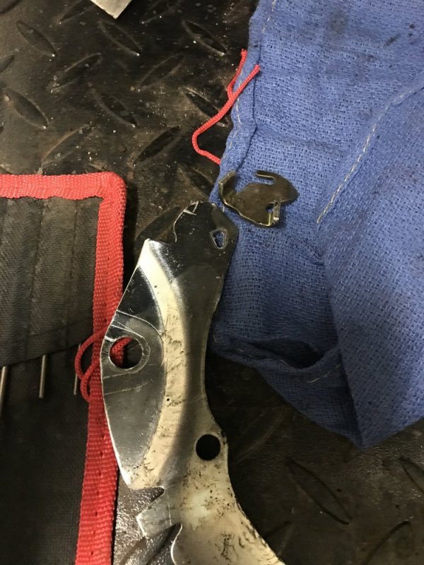
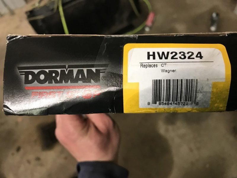
If you’re going to be doing rear brakes, do yourself a favor and DON’T get the Dorman hardware kit. It had lots of problems. I had to reuse my driver side adjuster because the swivel side of the Dorman one wouldn’t slip together all the way.

B60B9B1C-B8B1-4D2D-A660-51652407F96C.jpeg

On the passenger side, the adjuster pieces wouldn’t fit together so I had to reuse the one that was on there. Good thing the hardware on the truck wasn’t too old.

CF948D64-63FB-4FD3-974F-3D0304E8E2EB.jpeg

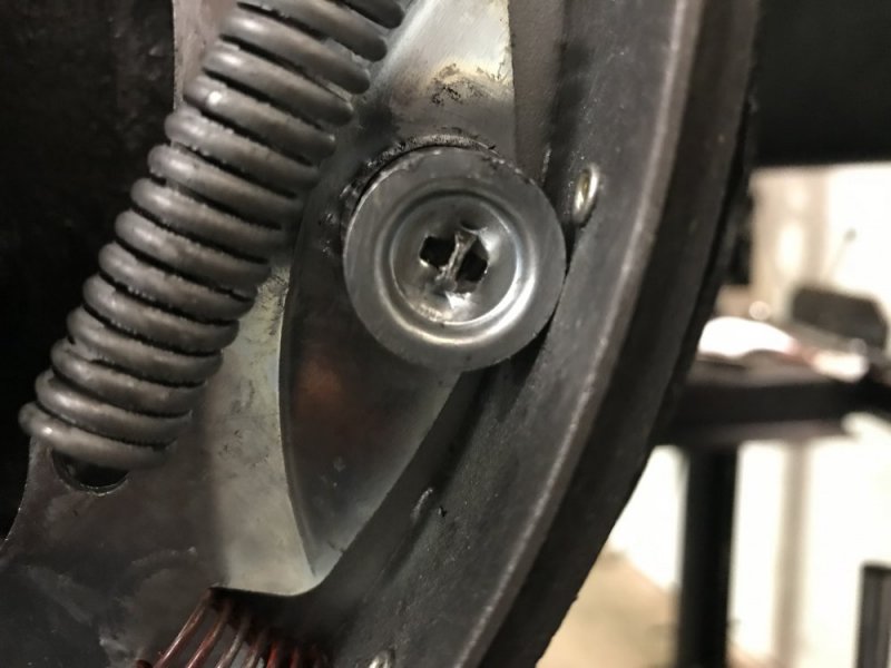
And a gripe regarding the kit is that the spring hold downs don’t have ridges that engage the springs. So they were constantly popping off when I was trying to install the springs.

9C112134-CE8E-4E1B-B4F7-507C10230FD8.jpeg

Just stay away from the Dorman kit.

87A089FA-C472-4A35-A8EB-EB500790B2E6.jpeg

Tomorrow I’ll work on the fronts and do the braided hose install.
 
Some people say only the doorman electrical stuff is bad. I have found more junk from doorman wether electrical or mechanical than any other aftermarket manufacturer. I will not buy anything doorman unless there is no other option.
 
At a gear and driveline shop I went to years ago, a shop had a 240v motor that they hooked up to problem axles to run for noise testing. No clue how to
Deal with that gear problem other than write a check to a pro.
That used to be me, I was the diff guy who took care of the "problem child's". I worked at a dodge/jeep dealer in 00/01 which was the height of howling dana's and growling dodge gear's. Even have my own tool for adjusting the 8 1/4 & 9 1/4 backlash. Spent many a day using the set-up tool's for finding pinion depth, setting them up, get a horrible pattern, have it howl, then get the service manager to approve setup time to go in and actually set one up manually. Been a long time since I set one up though.
 
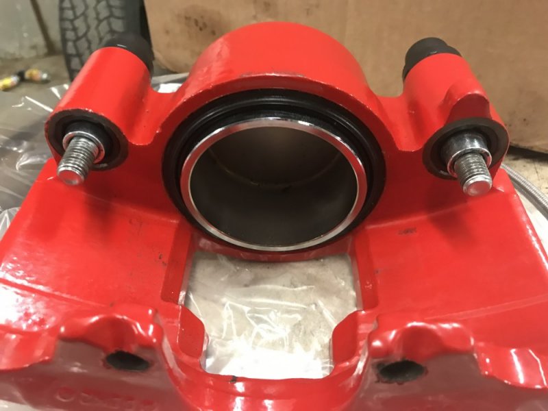
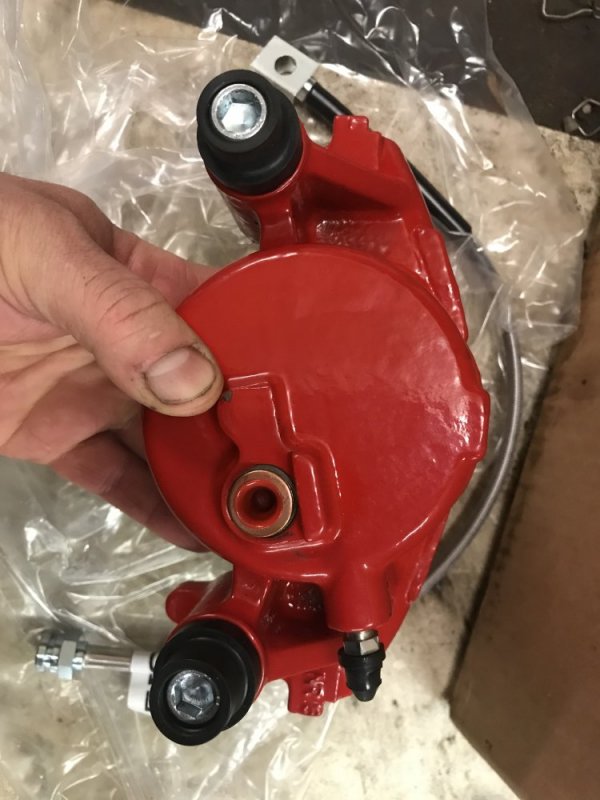
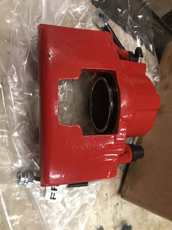
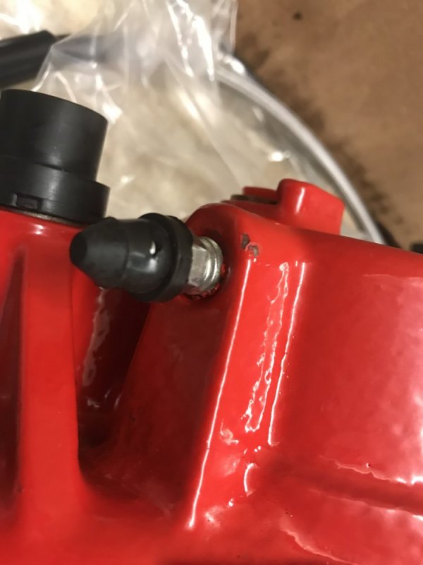
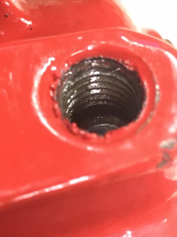
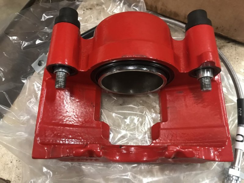
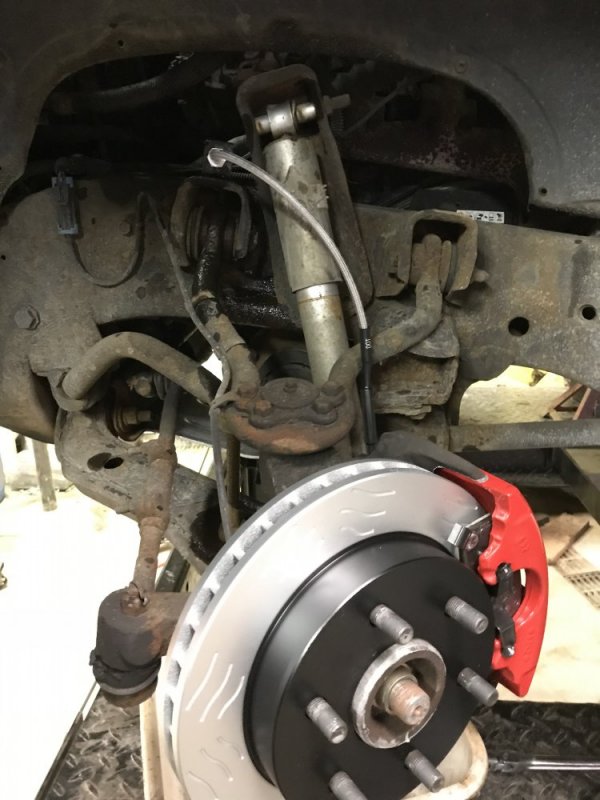
Starting on the fronts now. I just unpacked the Power Stops and figured I’d share my initial impressions. They look to be well-made parts. The pistons are either new or cleaned and chromed. I don’t care about them being shiny, but chrome seems like a good choice for a durable coating on them. The hardware looks good. The bleeders fit tight and have good threads. The red coating has a few chips in it, but whatever - the coating was a bonus. I also noticed that one of the bleeder caps had a tear in it, presumably from bouncing around in the box during shipment, so that’s a little disappointing. Overall I’m pleased so far. Oh and these are the 3/4 ton calipers so I can run larger pads. BC096416-8109-4DD9-B751-10D4CCCDF745.jpeg429D7F2E-B353-4ABF-87A7-C2A0050319F0.jpeg88DF8313-94EE-41AE-A921-14D9E6DF6348.jpeg22331560-B96E-469D-BDB4-9B7093AB0857.jpegA243BC93-240D-490F-B3A3-E64A901D7317.jpeg10A7A477-89ED-458E-908F-9C6F63BE18A3.jpeg
 
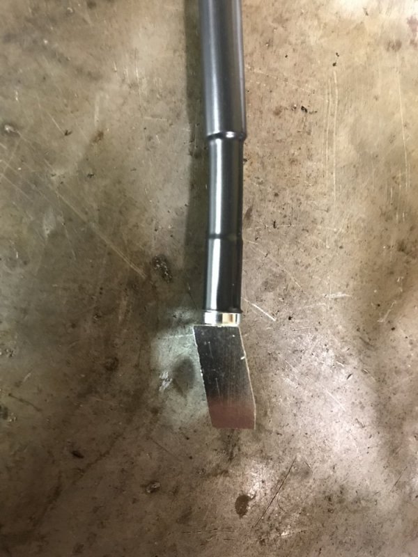
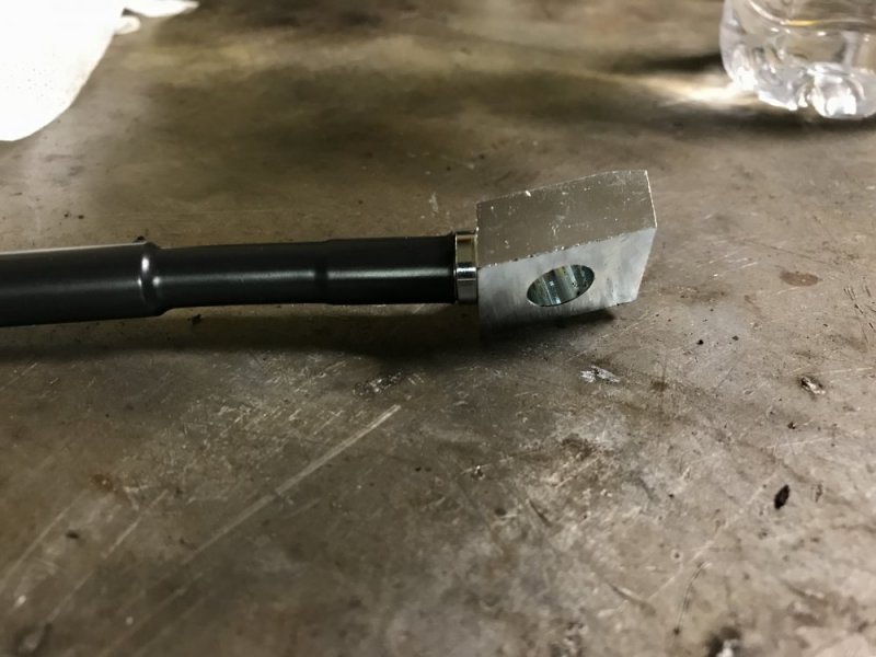
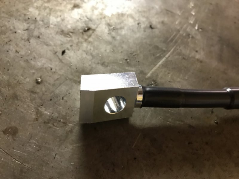
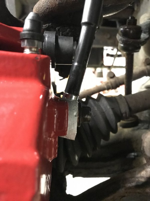
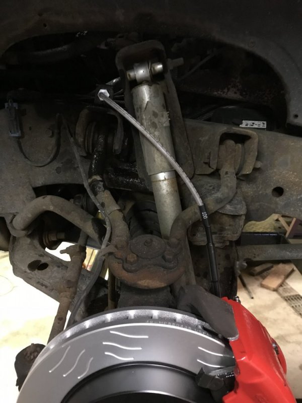
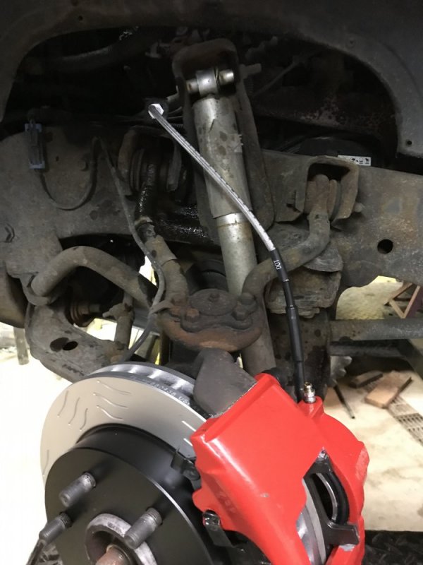
One side is together. The braided hose fits nicely. The fitting at the caliper is a bit different than the stock fitting - it’s machined with an angle built in. This keeps the hose away from the wheel once installed.

549E4980-91C2-44C6-871D-595CF312111C.jpeg F5EAA307-663D-4323-B548-F7BCBC814C41.jpeg 6D4A235E-B440-45A4-A5AF-C8D8616DA0EB.jpeg DDFA77B8-2E83-409B-86D2-52FBC7EB5978.jpeg 315097BC-58F3-4DFC-B729-D64D726156E4.jpeg

I turned the wheel lock to lock to see how the hose reacts and it looks fine. I went to the junkyard yesterday to find some stock hoses to grab the bracket off of and that’s when I realized that the 4 wheel drive trucks don’t have a bracket. I’m going to see how this works and if it does develop a rub I’ll come up with some kind of a bracket to keep it away from the other parts.

2A7091FE-7185-4A12-BE35-0065C48BE5F6.jpeg 00B1FEFE-A852-403A-819A-3871D1DCA834.jpeg 44327A99-7430-4340-8FD9-DF91FB0BC476.jpeg

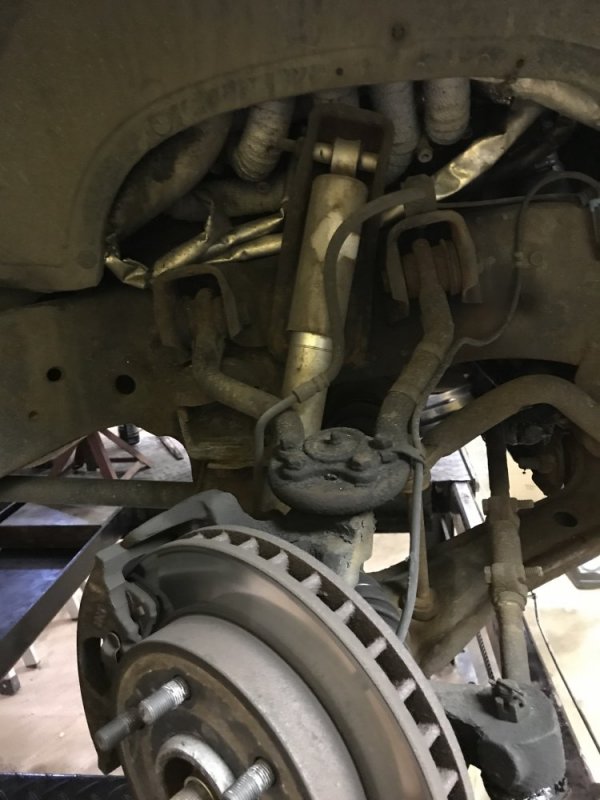
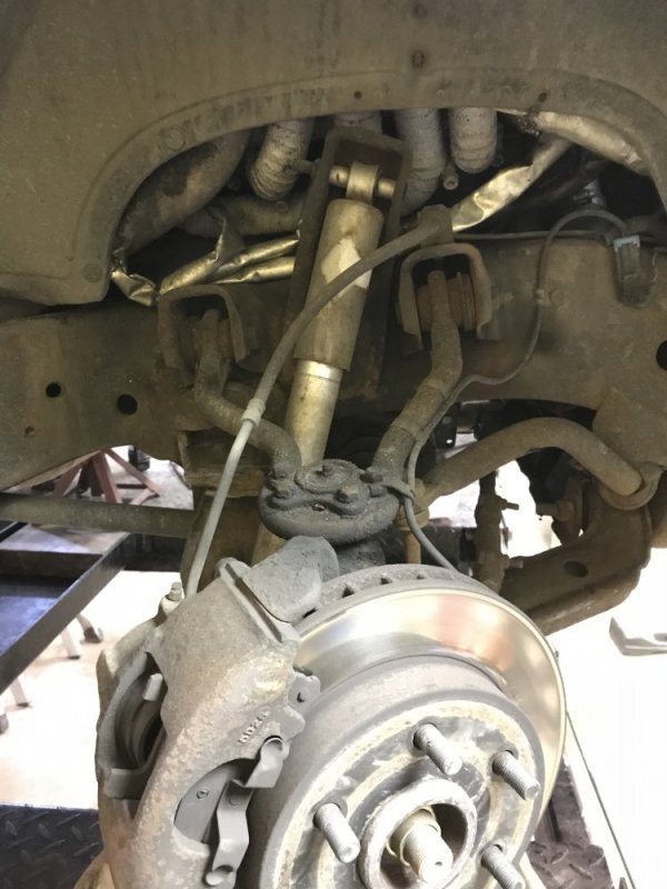
Here’s the other side with stock parts for comparison.

80E37166-B437-4034-BD66-6712F00034AF.jpeg 609FC4BF-EC8D-4FA8-984A-35B89536E057.jpeg

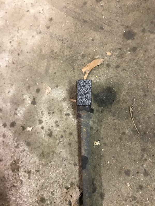
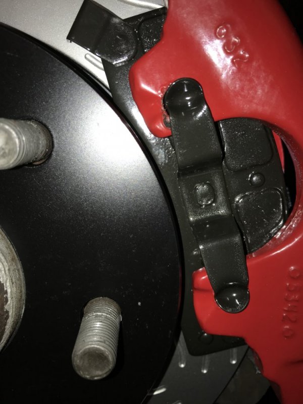
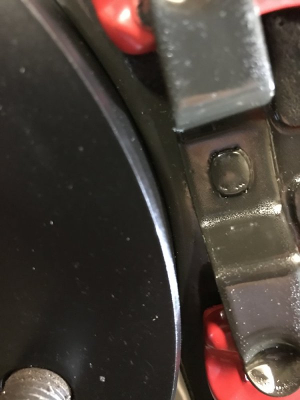
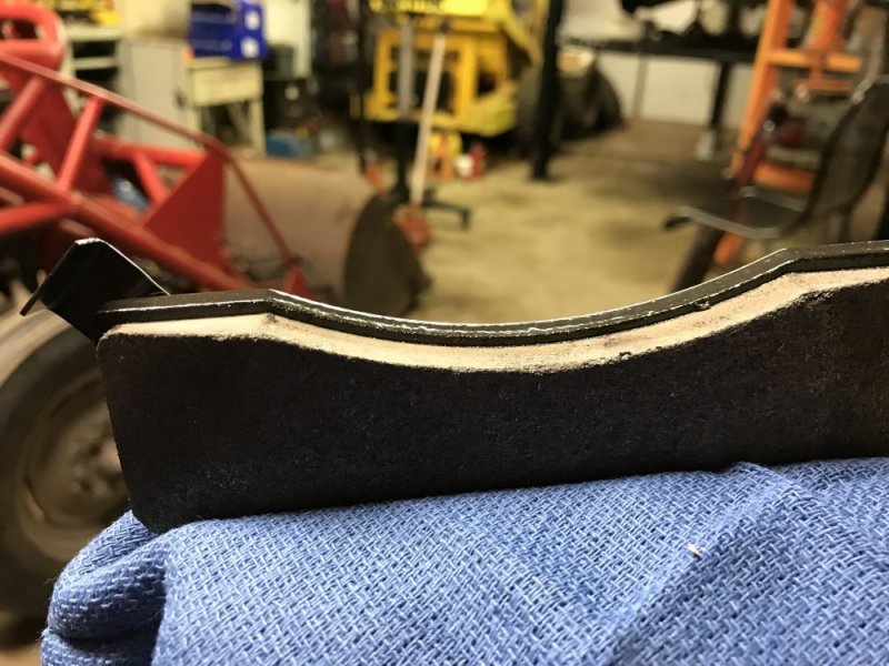
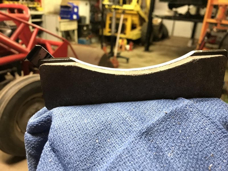
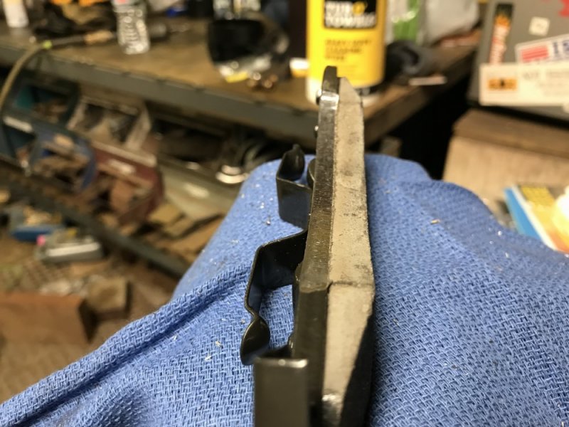
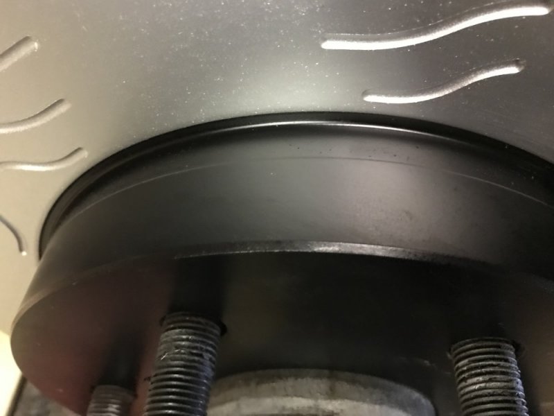
I did run into an issue with the 3/4 ton (370) brake pads. I installed the caliper and pads and noticed that the outer pad was rubbing on the rotor. I kind of remembered reading about that, so it didn’t totally surprise me. So I took the pad to the vise and went at it with the die grinder. I took the metal all the way to the friction material.


I thought that would be enough but it was still rubbing on the outer edge, so I ground it some more - putting a chamfer on it even. I reinstalled the caliper and it’s still rubbing toward the inside. I’m going to run it like this and seenif it wears in ok.

I could only fit the the hose pictures on this post, so the pad pics will be on a second post.
 
Here are the pad pics.

Before grinding

6E710AE4-93CA-46C6-A5F0-DA5CF99F4894.jpeg 0BFA0B63-B3DB-41FC-803B-FC584EAF2300.jpeg
A9B8205D-167B-423A-915B-641E730C9940.jpeg


These pad pics were after the first round of grinding, not after the chamfer. It was a shame to grind off that pretty ceramic coating.

FEA74561-8C98-4F8C-87E0-D5DA05644C67.jpeg C5145A97-9A9E-4E5F-8485-5628EB5B355D.jpeg

Here’s the witness mark from the rub. This is after the second round of grinding.

18C64E02-F057-460D-A697-173DFAE4FB31.jpeg
 
Thanks Leo.

Ok passenger side is done.

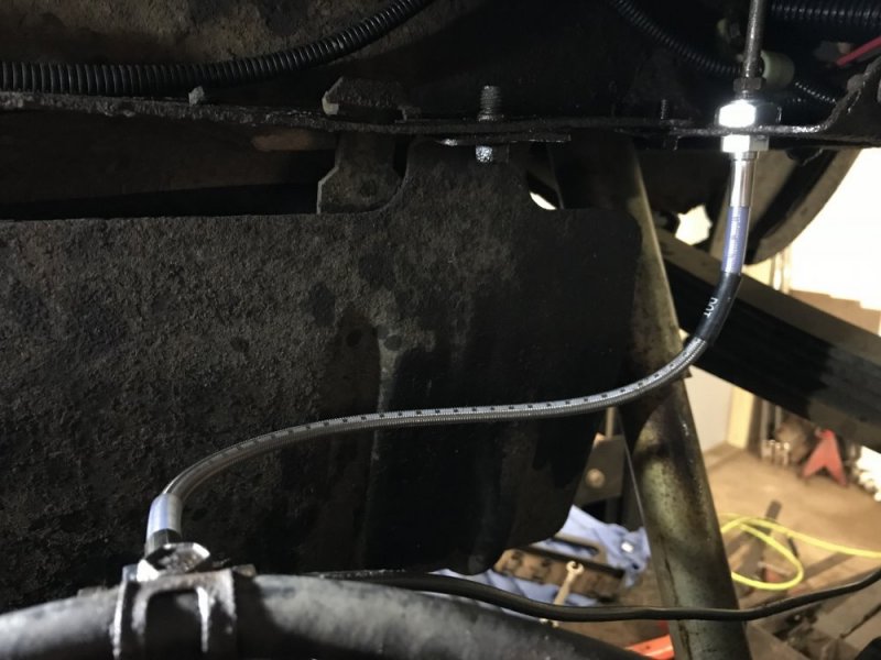
Last part was to install the rear brake hose. It has a nice hex nut for retaining it instead of the factory cheesy sheet metal nut.

AAD20F42-3DFE-4237-B244-309B43FB3091.jpeg

Now I’m flushing the lines with fresh fluid and bleeding the system of air.
 
I realized today how undersize these brakes are: I measured the rotor and it’s only 11-9/16s......they used to put 12” brakes on Caprices!! What was GM thinking with such small brakes on a truck??
 
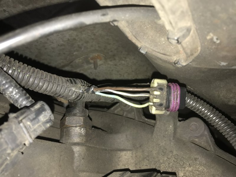
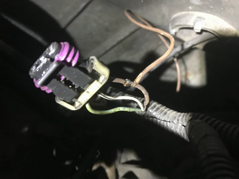
To wrap up today, I alternately opened bleeders to let fresh fluid flow through everything. While that was happening I hooked up the brown wire for the 4wd actuator. I found a thread on another site via a Google search that did a good job of describing which wire it was that you’re supposed to tie into, but no pics. I like pictures.

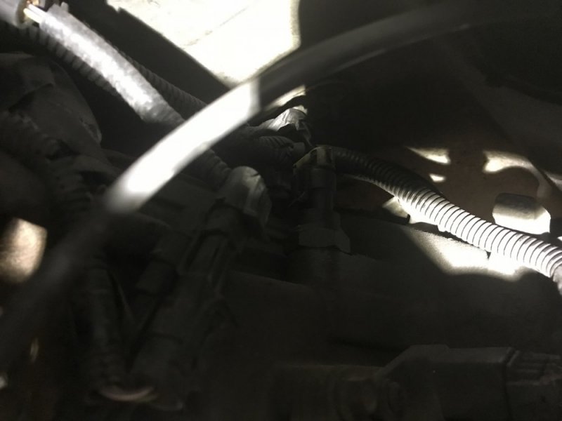
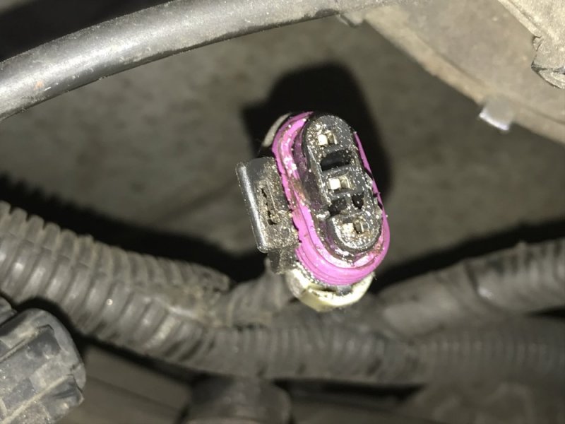
There’s a plug on the top of the transfer case. The plug has 3 wires going to it: Light Blue, White (or Light Gray?) with Black stripe and Brown. That’s the one.

E5E8478F-B925-49A5-A306-1A8138DA7AFF.jpeg 0A49255E-9755-42BC-B888-9096F8F6CA3E.jpeg 099BFFDB-F0E5-4F96-A526-1321DDB628C0.jpeg

I ran some 16 gauge brown wire over the transfer case to that plug and spliced into it. There are two other plugs back there - by unplugging those I was able to move the harness to a location that was easier to work on.

997A5452-433F-4665-8727-9B86621A553C.jpeg

Once it was spliced I just ran the wire up the transmission cooler lines and then down to the actuator plugs.

D357AECD-F962-4B3E-BC5E-B04256B29936.jpeg 360904E5-D112-4F79-86E4-3E33439EB648.jpeg

Eezy-peezy. Tomorrow I will do a vacuum bleed on the brakes to make sure all air is out. Then I will prep everything else so I’m ready to install the gears that are supposed to arrive Tuesday.
 
Oh and I found some interesting info. Apparently it’s not hard to swap the GMT800 1500 knuckles onto a GMT400 1500.....and by doing so you can take advantage of OEM brakes that are much larger. You can go up to 14” brakes, all with OEM stuff! You need 18” wheels to fit them, but still it’s cool to know that can be done. Here’s the thread I found. Unfortunately the pics don’t work, but still you get the idea. I saw a familiar name in the thread too!

http://www.gmt400.com/threads/nbs-front-brake-swap-for-obs-trucks.17805/

I’m too far invested in these brakes to do that now, but next time I need brakes I think I’ll go that route. I know some guys on here were doing that with the 2500s and 3500s, but I don’t think I had seen the info on the 1500s. If/when I do that, I will start a dedicated thread (with pictures) for the info.
It's pretty much just like doing the 8 lug trucks. Ream the ball joint holes, ream the tie rod holes, and bolt em on.
 
Thanks Leo.

Ok passenger side is done.

Last part was to install the rear brake hose. It has a nice hex nut for retaining it instead of the factory cheesy sheet metal nut.

View attachment 52734

Now I’m flushing the lines with fresh fluid and bleeding the system of air.

Nate, how do you bleed your brake system, just the two guy method or do you have another way?
 
Nate, how do you bleed your brake system, just the two guy method or do you have another way?
I use a manual vacuum pump and suck the fluid out through the bleeders. I can’t usually get a good enough seal to see when I’ve removed bubbles (because it draws air past the bleeder threads), so I just run enough fluid through the system that it had to have removed the air. I also like to leave the bleeders open for a while before I vacuum pump...letting things just gravity bleed, but I don’t love that I could be adding moisture to the system by having it open that long - it does help me get more fluid through the system though.

I made a home made pressure bleeder out of a sprayer, but I found that most master cylinder covers seal so poorly that I just ended up making a huge mess at the MC from all the fluid leaking past the lid seal. I had a gauge on the tank and it would leak at just 1psi sometimes. Plus you need a dedicated lid for each style of master cylinder for that method. So I’ve gone back to vacuum bleeding.
 
Back
Top