• Welcome to The Truck Stop! We see you haven't REGISTERED yet.

    Your truck knowledge is missing!
    • Registration is FREE , all we need is your birthday and email. (We don't share ANY data with ANYONE)
    • We have tons of knowledge here for your diesel truck!
    • Post your own topics and reply to existing threads to help others out!
    • NO ADS! The site is fully functional and ad free!
    CLICK HERE TO REGISTER!

    Problems registering? Click here to contact us!

    Already registered, but need a PASSWORD RESET? CLICK HERE TO RESET YOUR PASSWORD!

Rebuilding a GEP Engine

Bobby, do you have the part # for the correct clevite cam bearings?

The part number is SH-1366S, but the oil holes did not line up like they should. I actually bought two sets, both were branded Mahle. The first were made in Columbia and did not have the notch in the front bearing. The second set, the ones I used said Mahle Clevite and were made in USA. They did have the notch, but the oil holes were not oriented per the GM manual. Both the parts house and my machine shop said they were Melling Dura-Bond bearings in a Mahle box, which they tell me is common. I do know that its hard to find a specific brand of bearings as just because it says Mahle or Clevite or Vandervell on the outside of the box, there could be anything on the inside.
 
Did you also locate the hole in the rear cam bearing at 4:00? My stock 6.5 had the rear at 12:00. From the picture the front w/ two holes is at 6 & 4 ?
Thanks
 
Did you also locate the hole in the rear cam bearing at 4:00? My stock 6.5 had the rear at 12:00. From the picture the front w/ two holes is at 6 & 4 ?
Thanks

On bearings 2-5, the oil hole ended up at around 5:00. They were seamed bearings. I figured getting the seam at 11:00 was more important than the oil hole, so the seam was the determining factor.
 
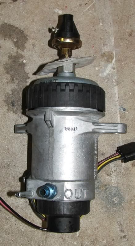
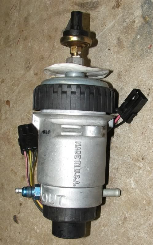
Here is my fuel manager mod. I installed a -6 AN fitting. I'll be running -6 AN hose (3/8") to the DB2 injection pump. Still have to sort out the fitting on the pump end, but that shouldn't be too hard. Since its a little tamer than the Feed the Beast mod, I'll call it "Feed the Ogre". That is a low fuel pressure switch on the top with a fuel pressure tap air bleed.

FuelManager-2.jpg


FuelManager-1.jpg
 
You know that low pressure switch wont give you much indication of filter condition being on the dirty side.

You are right, but its the easiest real time way to know condition of LP.
Also if you have a aftermarket LP that can put out more than say 10 psi then it can give an indication of filter.
 
I always thought the flow was from the outside of the filter to the center. If I screw that out of mine, I can see straight down to the stand-pipe for the heater and outlet.
 
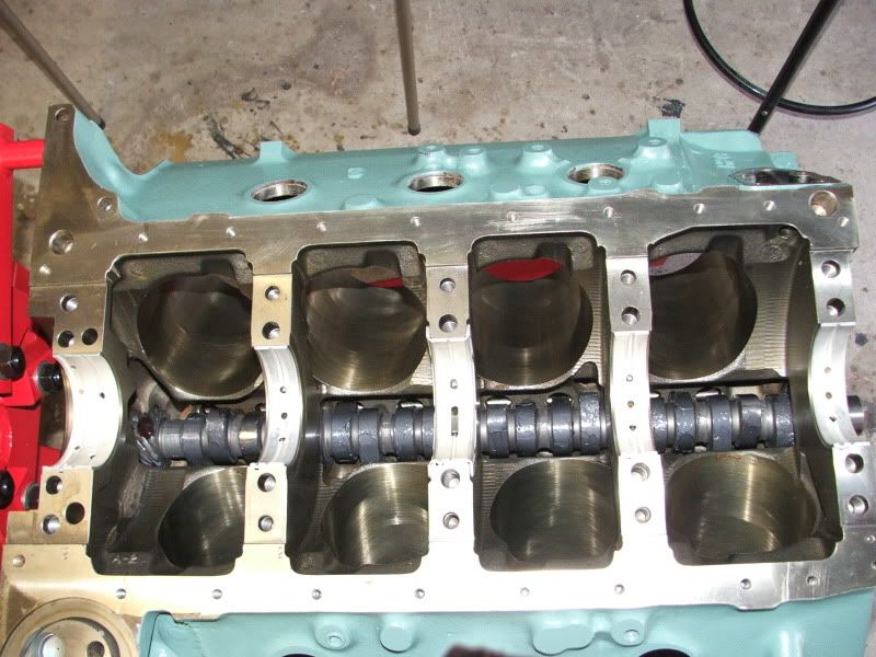
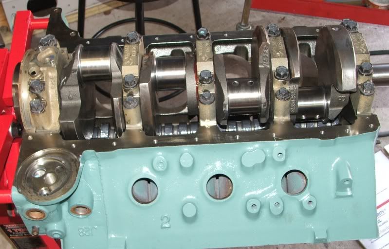
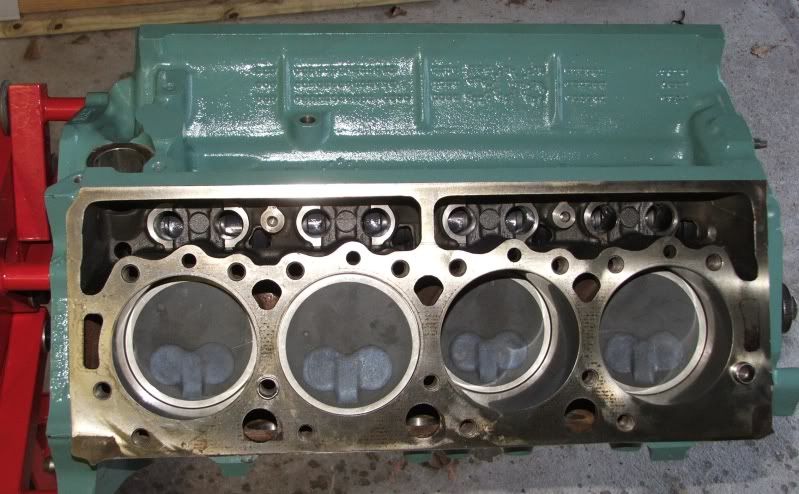
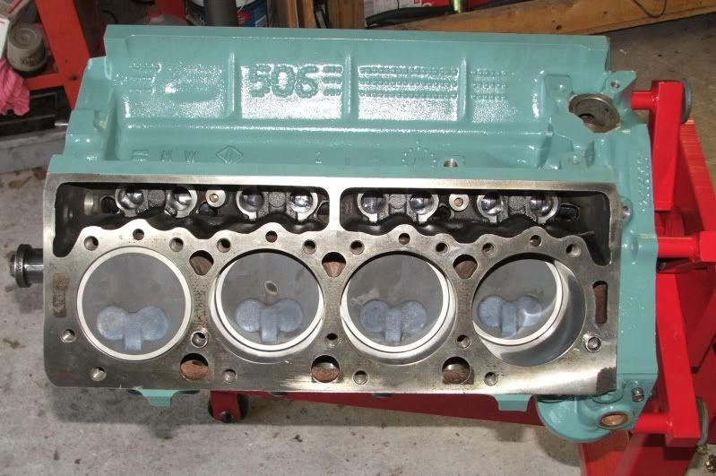
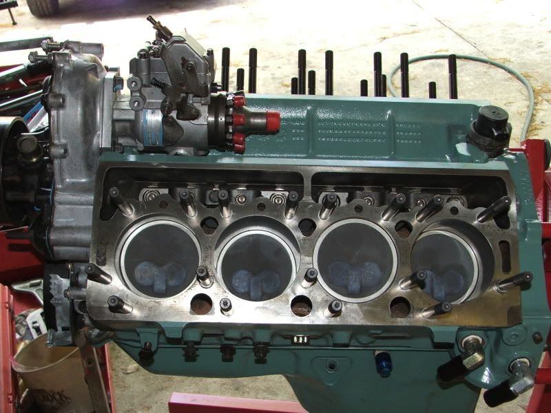
Actually got to assemble some parts this weekend! Got the cam, crank, pistons & rods all in the block. The main bearings were all at .003" That is a little more than I wanted, but within spec. The rod bearings all checked at .002, so very good there. The pistons have .010 reduced deck height, but are only about .002-003 down the bore. I would have liked more, but it is what it is. Hope to get the old engine out next weekend, so not sure how much more I will get done on the GEP this week.

GEPCamIn.jpg

Cam in, lobes have cam lube, main bearing shells with oil squirter holes.

GEPCrankIn.jpg

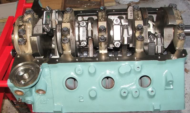
Here is the crank in with the main bearing caps torqued.

GEPPistonsin1.jpg

GEPPistonsin2.jpg

Pistons & rings in

GEPPistonsin3.jpg

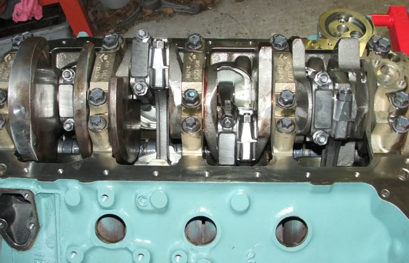
Rods & bearings all in and torqued up.

GEPPistonsin4.jpg

If you look at the first crank throw, you can see the Mallory metal added to balance the crank.

That's it for now.
 
As I said, I have never seen one, but this is highly unlikely. First remember the block was not originally designed for the center turbo, it was added later. So all the main oil galleries were designed prior to the center turbo feed. And not all the blocks are designed to have a center turbo. It is much easier to drill all the blocks the same and then drill the center turbo blocks with the additional holes. I'm not saying they don't do silly things, but it just wouldn't make any sense to have the oil from the turbo lubricate something else. I'm sure the drain hole is just that, a gravity drain back to the oil pan.

I have one here right now, I get it back tomorrow and will report back. I would either drill, tap and plug the ports or do as first suggested, make a plate and block it off. They won't use the return to lube anything, its just a drain.
 
The turbo oil feed is taken right from the oil galley that the OPS is on and the drain puts the oil right back at the rear lifters.

Block will be a different casting due to the way the rear mount is cast and the galley's.
 
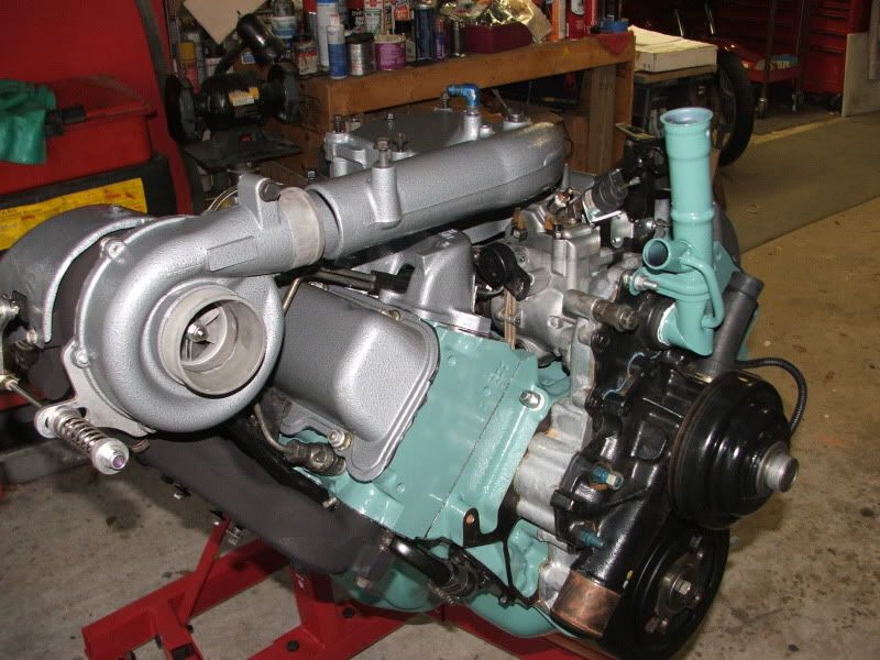
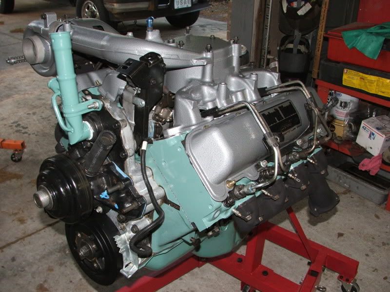
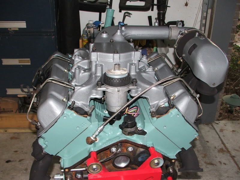
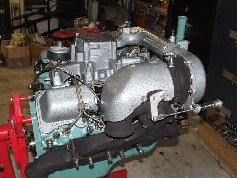
The engine is pretty much assembled. Still have a few things, like the intake and turbo to bolt on. Hope to install next week. No real problems with the assembly, but I did discover a few more things. First, the motor mounts take metric bolts, the original 6.5 bolts are grade 8 SAE. I also discovered the water pump backing plate is different for the GEP NA water pump vs the reverse rotation pumps. I had the GEP one all ready to go, but had to use the original backplate from the Sub at the last minute. Other than that, no real surprises.

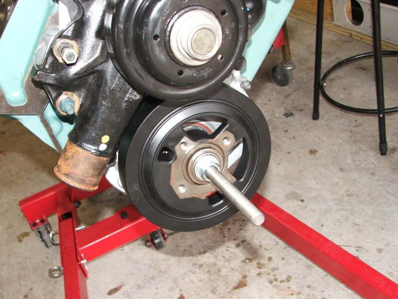
GEPdamperinstall.jpg

Installing the damper with my home made damper installer

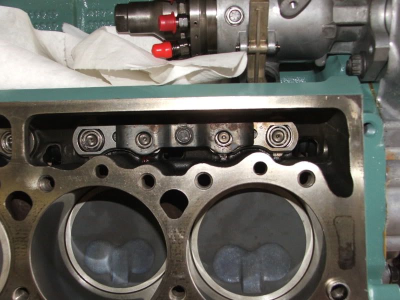
GEPLifters.jpg

Lifters and retainer bolted in

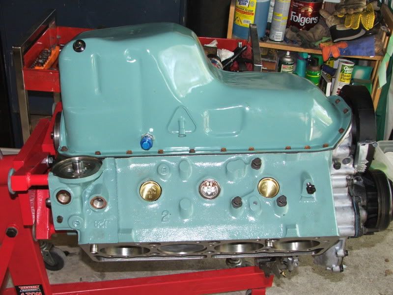
GEPFreezeplug-heater.jpg

New freeze plugs and block heater.

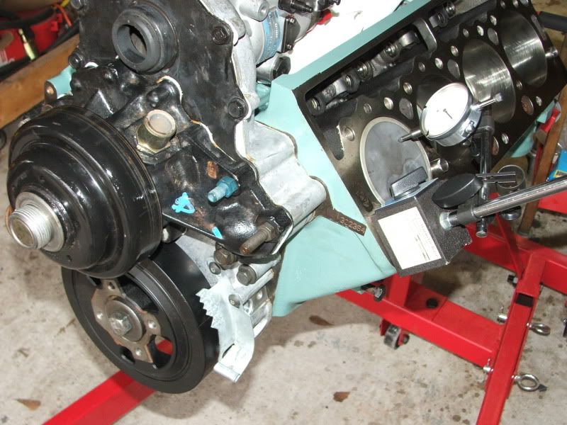
GEPTimingTag.jpg

Getting the timing tag set to TDC.

GEPHeadstuds1.jpg

ARP head studs in. I used GM thread sealer, so hopefully no leaks!

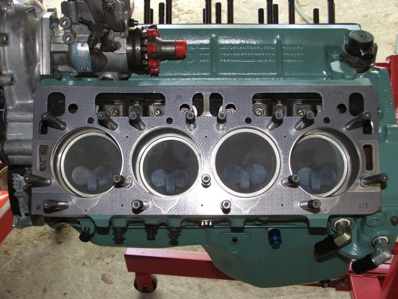
GEPHeadgasket.jpg

Fel-Pro head gaskets

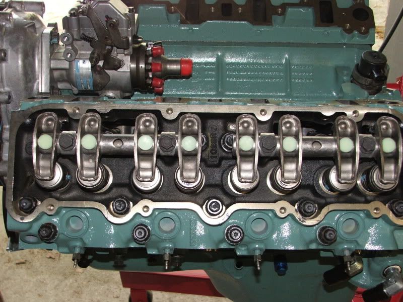
GEProckerson.jpg

Heads torqued down, rocker arms in

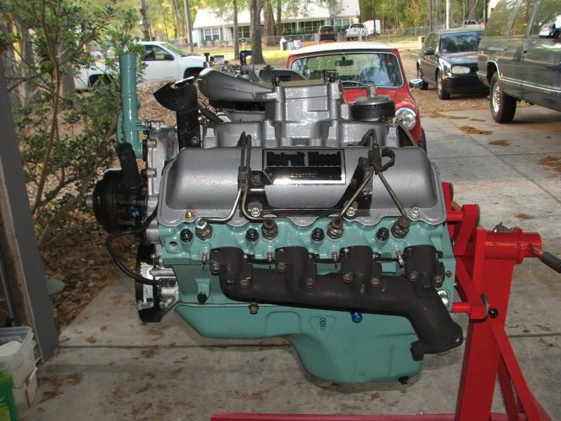
GEPengine04_04-1.jpg

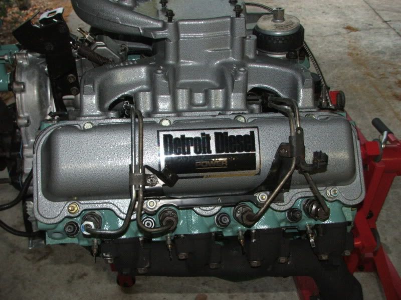
Here it is assembled. Intake is just laying on the heads, not bolted on yet. Glow plugs, injectors & lines installed, exhaust manifolds are bolted down.

GEPengine04_04-4.jpg

I'm changing the CDR a bit. Instead of using the valve cover, I'm going with a oil fill vent.

GEPengine04_04-5.jpg

Yes, I made a trip to the powder coaters! Oil fill is a combination of two fillers. The vented fill had the lower height fill with the older type cap. I had the tall filler with the newer type cap. So I cut them in half and had a friend tig weld the relevant pieces together. I now have a tall vented oil filler!

GEPengine04_04-2.jpg

I have changed around the fuel pressure sensor on my fuel manager, I'll try and get a picture before its bolted in. Stainless oil line is for remote mounted OPS sensors.

GEPengine04_04-3.jpg

GM-8 Turbo is not bolted down yet.

GEPengine04_04-6.jpg

Detroit Diesel Power!
 
Very nice.:thumbsup: Why the temp switch on the passenger side rear head? I take it the silver is powder coat?
I had the motor mount bolts mess with me too because the 10mm thread chase didn't want to turn in. Bell housing bolts are 10mm also. Through bolts on the motor mount are 7/16":confused::mad2:
I like the decal on the valve cover:thumbsup::thumbsup:
 
Very nice.:thumbsup:
Thanks!
Why the temp switch on the passenger side rear head?
Its the cold start switch for the DB2 injection pump.
I take it the silver is powder coat?
Yes, its Hammertone silver powder.
I had the motor mount bolts mess with me too because the 10mm thread chase didn't want to turn in. Bell housing bolts are 10mm also. Through bolts on the motor mount are 7/16"
Yea, I already bought the metric studs for the transmission mounts. On my original 6.5, the motor mount bolts are SAE, I think 3/8". The GEP is 10mm X 1.5, which is very close to the SAE bolts, in fact they will thread in quite a ways, so that kind of caught me off guard until I figured it out.
I like the decal on the valve cover
Thanks, I found those on eBay - from Australia!
 
The reason I asked about the temp switch is that my 92 and 93 both don't have that. Only the temp switch on the crossover. My 91 6.2 had the switch on the head besides the switch on the crossover.
Looks like you went to the ends of the earth to find parts:thumbsup:
 
The reason I asked about the temp switch is that my 92 and 93 both don't have that. Only the temp switch on the crossover. My 91 6.2 had the switch on the head besides the switch on the crossover.
Around then they went to the crossover for the sending unit. Its much easier to get to. I'm using the crossover for the temp sensor for the PCM, it uses it for the glow plug control. So I have 3 temperature sensors, one in each head plus the crossover.
 
Back
Top