• Welcome to The Truck Stop! We see you haven't REGISTERED yet.

    Your truck knowledge is missing!
    • Registration is FREE , all we need is your birthday and email. (We don't share ANY data with ANYONE)
    • We have tons of knowledge here for your diesel truck!
    • Post your own topics and reply to existing threads to help others out!
    • NO ADS! The site is fully functional and ad free!
    CLICK HERE TO REGISTER!

    Problems registering? Click here to contact us!

    Already registered, but need a PASSWORD RESET? CLICK HERE TO RESET YOUR PASSWORD!

CKO Provent 200 Oil Catch Cans

Oh, I see now. I had to look at the service documents to spot it, but they reversed the inlet/outlet positions so that it pulls air up through the filters. IDParts has the 200 unit listed for 179.95 right now. https://www.idparts.com/mann-provent-200-ccv-filter-assembly-395-s02-1239537s02-p-16275.html

If I didn't just buy a new CDR less than 10k miles ago I'd consider getting one.
So You would not run the CDR to the new pro vent ?

Interesting that they reversed the inlet/outlet hoses.
Without going back through many posts, I believe it was @dbrannon79 had mentioned doing just that but then also mentioned possible problems with a valve too.
 
And so the problem with the forum software continues.
I get that message about a problem and the reply cant be posted and then I tap the button again and get this message
IMG_9012.png
And so I scroll back up and my post is not there so I tap the button again after the XX amount of seconds then there is two posts the same.
 
I left my CDR in place since the knock off provent didn't have a valve on the outlet side. it only has a relief on the top under the cap. I think with the real provent we shouldn't need the CDR.

I just finished up the truck. pulled out the inner fender and removed that hose the PO had for the turbo oil drain and installed the factory pipe. Idk how he did it, but he had cut a factory turbo drain pipe short and installed it backwards so the pipe pointed away from the exhaust manifold. He also somehow used 5/16 sae bolts on it, when I had the turbo off I found that area was leaking. the threads weren't damaged but are a M10 thread. I went digging in my bolt stash and found two that fit much better and was able to sinch down on the flange for the drain. Now it has the full length drain pipe that snakes behind the exhaust manifold and butts up to the one down on the block with a short section of hose joining the two like factory.

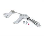
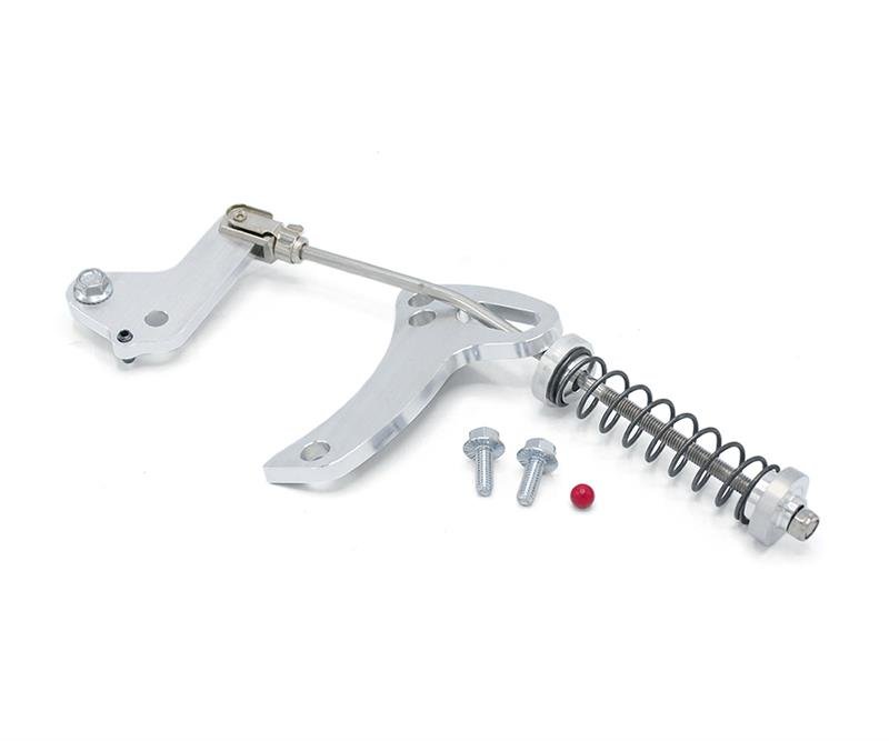
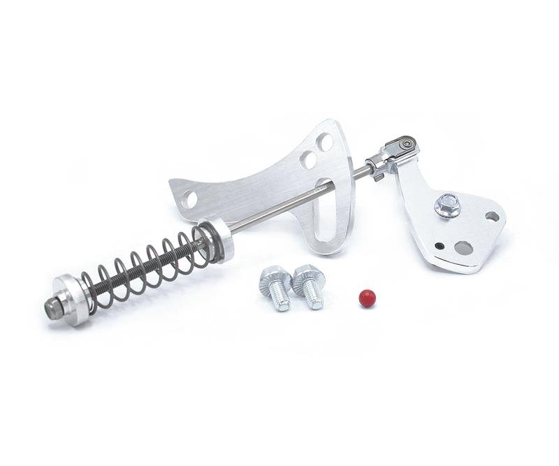
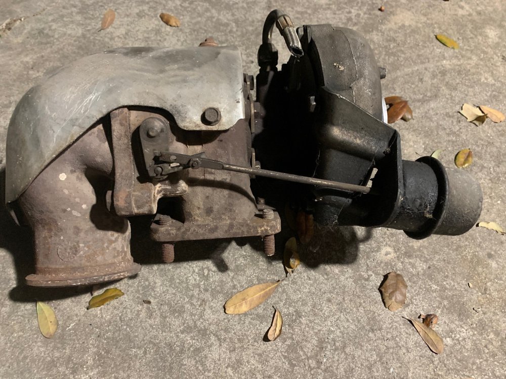
I also pulled the turbo off and checked the exhaust side and gave it a good look see. I was going to swap it out for the GM4 one I have but the TM would not work on it. the PO thought this turbo was a GM8 but after cleaning the tag on it i see it's a GM5 turbo. I have not seen nor heard of a GM5 before. Oh well, I had to put it back on.
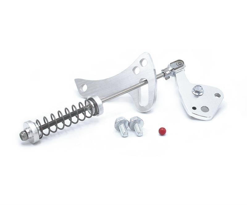
I have my home made TM that I no longer will be using.
I will box and mail that to You if it is something You can use.
I used it several times on My 2000 with the GM8 turbo.
I cant remember if it mounted horizontal or if it bolted on vertical.
IIRC, vertical was the answer.
 
I have my home made TM that I no longer will be using.
I will box and mail that to You if it is something You can use.
I used it several times on My 2000 with the GM8 turbo.
I cant remember if it mounted horizontal or if it bolted on vertical.
IIRC, vertical was the answer.
A vertical one I think should work for the GM-4 turbos. the one I have bolts on and points to the front. if you can, post a pic of it and I can tell. the reason the one I have wouldn't work is due to the position of the actuator arm position on the turbo. the one on the truck points towards the front when in the closed position, this one points down.


I looked on their site and they show two styles. I have the one in the first pic. the second pic works for the GM-4 I have.


1708667706861.jpeg

1708667747910.jpeg
IMG_4921.jpg
 

Attachments

  • 1708667771428.jpeg
    1708667771428.jpeg
    24.2 KB · Views: 0
That might not work for the older turbo I have due to the position of the actuator lever. Hang on to it though. One of these days if that day ever comes for me to convert mt 95 to all mechanical I might need one :)
 
Well today was a success, sort of.... A buddy and I drove the truck out to the pick a part yard, the truck drove flawlessly. quiet and smooth. the trip was about a 60 mile round trip on the freeway. I checked the oil once we arrived there finding it still full, and then again once I got back home. it lost about half a quart. opened up the provent to find the screen filter saturated and only a small amount in the soda bottle I ziptied down on the frame attached to the drain hose.

It's almost low enough to try adding some of the restore snake oil that Will suggested. I need to order a real filter for it and see if that works better. the clear hose coming off the CDR you an see oil standing in it at the low spot.

I am curious about what @Twisted Steel Performance had mentioned about the CDR connection on the oil fill pipe and the mesh thats in the valve cover where it normally goes. I wonder if I was to swap out the oil fill pipe it had to the one from the 6.2 which has the connection for the CDR there if that will not pull as much oil from that location while plugging the hole on the valve cover.


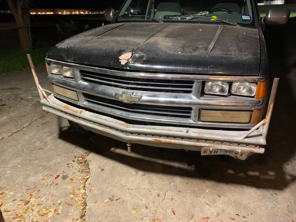
While I was at the pick a part yard, I snatched a tail pipe for the exhaust so that I can have it come out behind the tire and not blowing soot up on the bottom of the bed. got that cobbled in. I also scored a complete front grille made for the composite style headlights. installed the quad sealed beams that was originally on the truck and got the grille installed. I will have to remove the homemade front bumper to complete the install unless I can tweak it slightly on the passenger side as it's been bent and has also bent the lower part of the fender. I will look at that tomorrow sometime.

Here is the almost finished product. I need to drimmel out some on the inside where the upper side reflectors are to make it fit flush, but it looks good!

IMG_4922.jpg
 
The cdr port at the fill tube is good but you have to also have the oil slinger gaurd inside for it or else the oil will come off the timing chain and get splashed out.

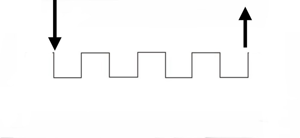
Something that will help is if you could make a repeating pattern that allows airflow but has multiple direction changes to promote any liquid oil to be trapped before getting to the catch can it might help. I was thinking 1” tubing with offsetting walls (see pic).
Basically use it in place of the hose that goes from valve cover to provent.

IMG_0219.jpeg
 
where is the oil slinger guard? inside the tube or under the cover that bolts to the water pump? I did look at the tube that has the connection and there is a sort of half baffle in there
 
I found a photo of the guard. I will have to look to se if the PO installed one in there.

I found this thread showing this issue on the same truck.
 
The cdr port at the fill tube is good but you have to also have the oil slinger gaurd inside for it or else the oil will come off the timing chain and get splashed out.

Something that will help is if you could make a repeating pattern that allows airflow but has multiple direction changes to promote any liquid oil to be trapped before getting to the catch can it might help. I was thinking 1” tubing with offsetting walls (see pic).
Basically use it in place of the hose that goes from valve cover to provent.

View attachment 86376
I wonder, if a person developed something like whats in this picture, then shoved it into the hose between the CDR and the catch can if that would slow down the vapors and help the oil fall out while keeping it flowing towards the catch can.
 
what effect would a "Y" pipe or hose where crankcase gasses were being pulled from both the valve cover and the oil fill tube into the oil catch can. the flow would speed up as it entered the provent but would be slow moving from the engine as it would split the amount being drawn between both areas. just a thought.
 
what effect would a "Y" pipe or hose where crankcase gasses were being pulled from both the valve cover and the oil fill tube into the oil catch can. the flow would speed up as it entered the provent but would be slow moving from the engine as it would split the amount being drawn between both areas. just a thought.
Probably would need a check valve in the bottom of the Yd hose to keep it from sucking in air.
Oil flowing to the pro vent could drop out and get drained then recycled back to the engine.
 
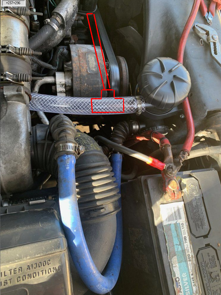
Here is what my thought was... adding a Tee and another 1 in clear hose over to the oil fill tube (using the 6.2 fill pipe) also eliminate the CDR on the valve cover and use a 90deg fitting so both are free flowing. put the tee as close to the provent as I can so the flow only speeds up past the tee. I don't think it would make any sense to run two CDR's because the turbo would never be able to pull enough to close both at higher boost pressures. I could put some kind of spring valve to open air on the rubber elbow connected to the blue hose here so that in the event the suction gets too strong pulling through the provent it can open and not put the provent into a vacuum, but then again not so sure that would be needed.

I was also thinking I need to shorten the blue hose that I have looped in the photo so that it going upward to the intake tube. this would also have a "draining" effect where any oil that condensed in this hose would drain back into the provent and fall down to the provent's drain hose.

1708766447559.png
 
there's no doubt this engine is worn out due to blowby. later down the road I am considering one of two options.. pulling this engine and at the very least seeing what my chances are about doing a re-ring job on. or look at seeing if the 6.2 engine is worth dropping in this truck.

I am sure that if and when I pull this engine I will find cracked main webs and not want to take the chance disturbing them. pulling the pistons and doing a re-ring job might make it last a while longer. it's a shame that this thing now runs so well and had good power even with all the blowby it has.

I will do a compression test before I do ether of these options.
 
To really be able to slow it down you need a container with a large volume. The prevent probably works well with lesser blowby but with lots of blowby I'd be surprised if it helps much.
 
IMO the biggest hurdle to overcome is the speed of the vapor. Needs to be slowed down in order to coalesce and fall out of suspension.
Yes- slowing the flow SPEED is good, so long as the volume is maintained.

Without dragging everyone through chem class, it is basic chemistry 101.
I could find a one or two page link if folks want that explain it better than I can, and much quicker I am sure. I have the information, I lack the language skills to express my info, as y’all unfortunately witness too often.

There are two things that cause a phase shift gaseous to liquid, liquid to solid:
Temperature and pressure. Think steam, water, ice. The easy control is temperature. Add heat to make solid ice go to liquid, more heat goes to gas phase as steam. Cooling it does the opposite. The problem is to cool the “boiled” oil back to solid would take a tremendous drop in temperature, while any amount of cooling that occurs is not bad, effort or expense to cool it isn’t going to bring much results. So running hoses, catch cans, etc away from heat isn’t just smart because heat plus oil equals fire, but getting the stuff cooled off will help.

Is it worth building a copper coil out of 1/2 tubing as the line from the cdr (or cdr location) so the passing airflow cools off the 25’ coil of copper before it gets to the provent? Idk. Maybe depending on the individual.
What about putting the coil of copper in a box of water so it forces the oil to cool- then you need a radiator and waterpump to circulate the water to remove the heat from the water which is cooling the coils. Idk. Maybe, depending on the individual.
Both would help and the water cooled system definitely would work better- but it a week of fabrication, hundreds of dollars in parts, turning the rest of the area int a non serviceable area worth all that?

Pressure is the other way. That is how the provent canister and filter work. The filter slows the flow of the gases enough to make SOME of the gaseous state oil vapors change into liquid. The design of the filter media captures the vapor as it transitions to a liquid form and wicks it away from that transition area down the housing and out the drain tube.
Honestly a compressor is far more effective, but a compressor that would do this and not be damaged over time, be cheap enough to be justified, this brings me back to several years ago when I brought up dry sump systems. A happy medium might be- if a guy has abandoned the belt driven vacuum pump because he wanted manual control over turbo boost, but the pump is still working and in place. First you need to know if it is just a bladder pump and not one that could ignite a fire. Assuming it is a bladder pump, then run copper line from the cdr location down under the truck along the frame away from the exhaust. Have it make a long route under the bed and back up towards the engine compartment.
then into the catch can, which has the other side hooked not to the inlet horn of the intake pre turbo- but instead hooked to the vacuum pump.
The miles of copper tube under the bed will give plenty of time to cool temperature, then any remaining vapors collect in the can- and the vacuum pump is simply the driver.

Or you might test and find going from the engine directly to the vacuum pump creates enough pressure in the oil mist filled gas that it compresses the oil into a liquid state. Have the catch can after the compressor.
The problem with either of these two options as a realistic test is the fire potential in the pump.
 
The Y idea and pulling from two or more locations out of the engine is good and bad.
Your turbo creates a limited amount of vacuum. Pulling from one area is easier with a small vacuum source. One are creates higher pressure coming out of the engine which helps drive the gasses flowing.
Pull from multiple areas- imagine you had 20 hoses tied together- first the hoses all have to be sized so the vacuum from the turbo is equally spread across them or it will pull much from one and little from another.
but with just two sources- and since your engine is producing way more than desired or normal pressure - maybe it works out.

Playing around with hose lengths including how close provent is to turbo inlet could bring good results. A cheap manometer could prove useful.

The draw back could be whichever location has more oil in mist form could become the primary source. If you already had two valve covers mounted that had ports- and already had the filler spout with splash gaurd installed, heck yeah a couple minutes of playing around with hoses could definitely prove to be beneficial.
But you are going to have to spend money on parts and time swapping things around before you can begin experimenting.

Remember the pressure in the engine is the enemy. All the filtering to catch the oil is higher risk to blowing out oil gaskets on the engine. So you want as much vacuum as you have pressure, actually more vacuum than pressure. This is why the blow off valve exists in the provent. Better to vent oil mist a couple moments than to over pressurize the crank case.

Les is 100% right in slowing the flow, and larger container being helpful.
Thats Boyles law in effect there.
Going into a larger container isa pressure change from high pressure into a low pressure. This causes a cooling effect on the mist going through. But it also becomes a restriction to flow- so if you could measure the pressure coming out of the valve cover under peak load, and measure vacuum created, compare the two to know your vacuum is greater than the pressure- all is well. The problem is- the Venturi created by the turbo is less.


Understand my back and forth line thing is creating length to cause the hot oil mist vapor to take longer to get to its destination. The longer flow time allows more cooling, and multiple minor pressure differentials to condense oil vapors while not restricting the volume of flow. Each change in direction eliminates laminar flow. The airborne mist that comes in contact with the edge of the pipeline can collect on it and drain back. Disturbing the laminar flow means the mist that was in the middle of the gas column going through will get into contact with the walls and help condensation. But is it still a form of restriction of flow. So doing something in that manner helps but too much will harm.
 
Back
Top