• Welcome to The Truck Stop! We see you haven't REGISTERED yet.

    Your truck knowledge is missing!
    • Registration is FREE , all we need is your birthday and email. (We don't share ANY data with ANYONE)
    • We have tons of knowledge here for your diesel truck!
    • Post your own topics and reply to existing threads to help others out!
    • NO ADS! The site is fully functional and ad free!
    CLICK HERE TO REGISTER!

    Problems registering? Click here to contact us!

    Already registered, but need a PASSWORD RESET? CLICK HERE TO RESET YOUR PASSWORD!

The Stealth BOMB'r is under the knife

ouch...is that due to the company that shipped them to you not packaging them correctly?

I have a feeling this is going to turn into a battle...I hope not for your sake...:(
 
I don't think it was either......

Let's just say I feel there is some shady 'ish behind it.

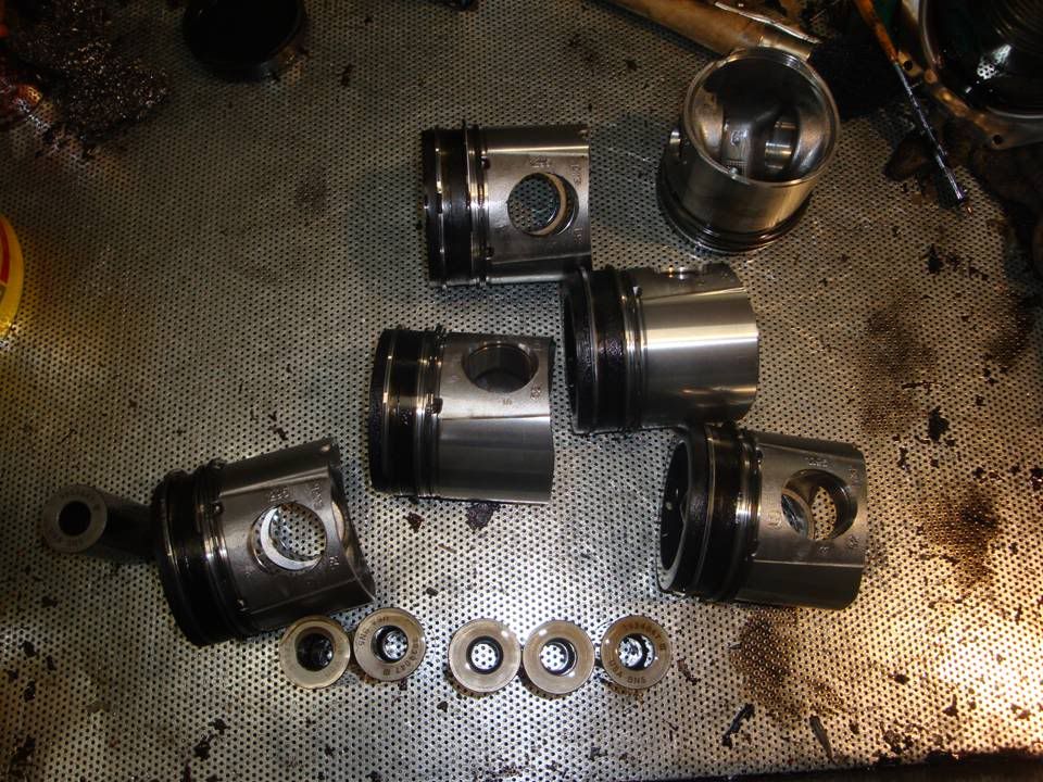
Ain't NO WAY ALL 6 pistons were damaged. These things couldn't have been better packaged if I put them in their own individual pillows. They went into the box with padding on the bottom and sides, 3 layers of padding on each piston, cardboard and packing foam between the 2 laters and packing on top. I SPECIFICALLY put extra padding on the piston crowns.

And yes, I had $1500 of insurance on them.

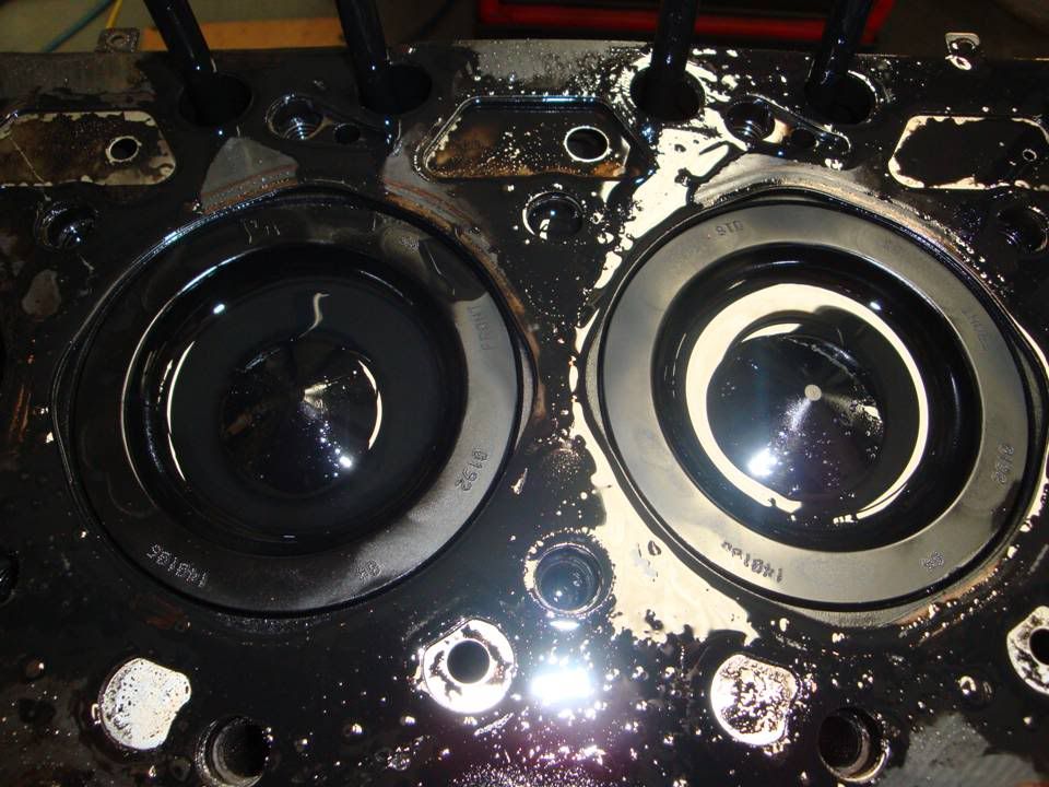
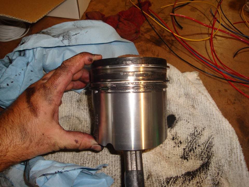
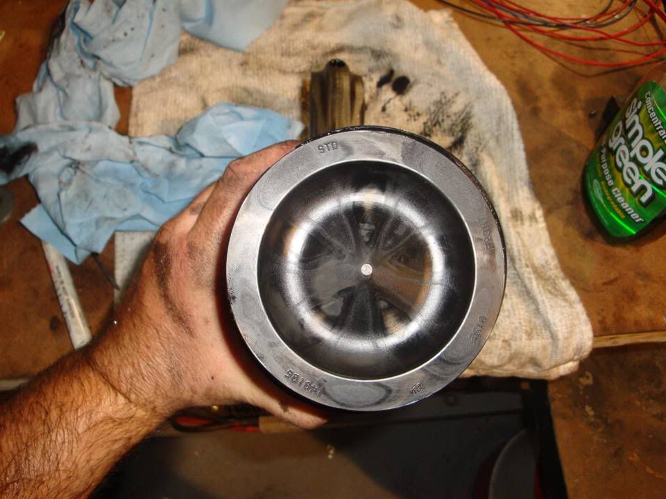
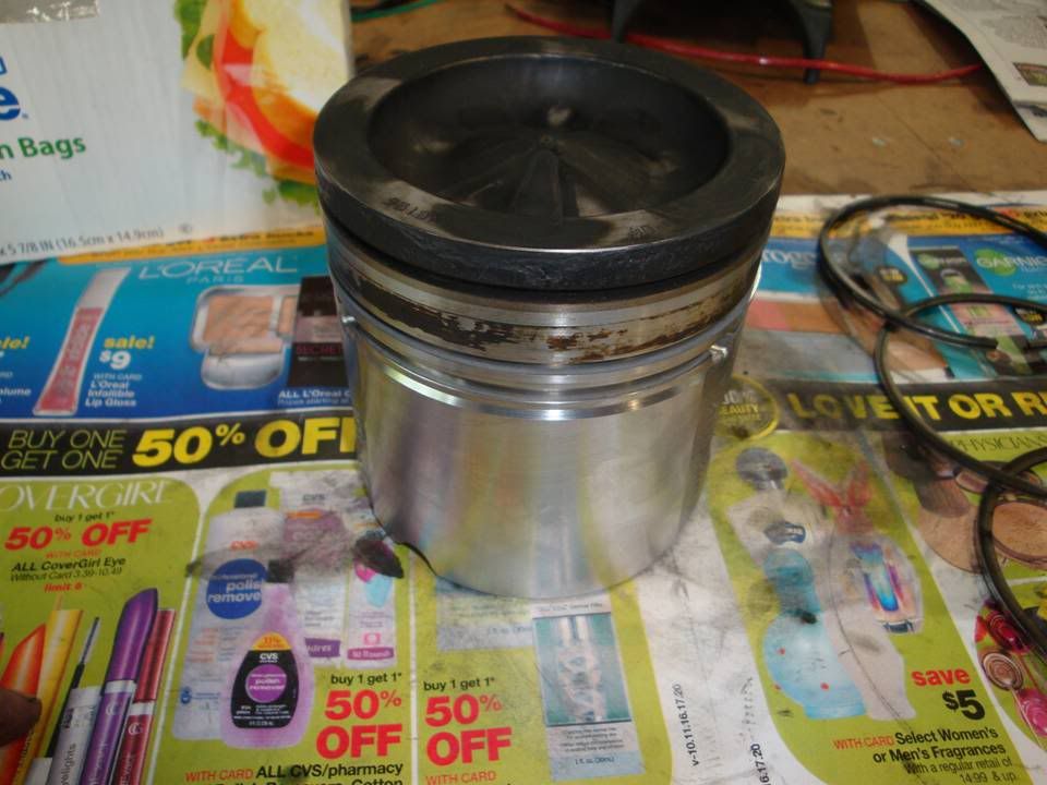
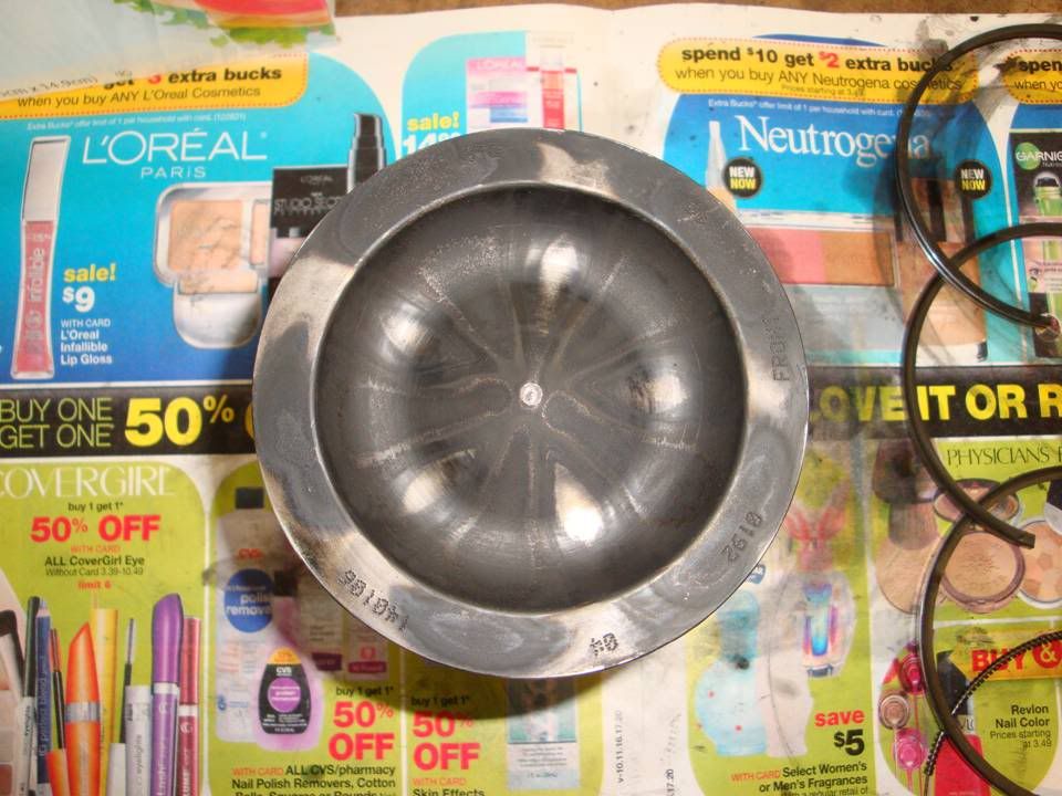
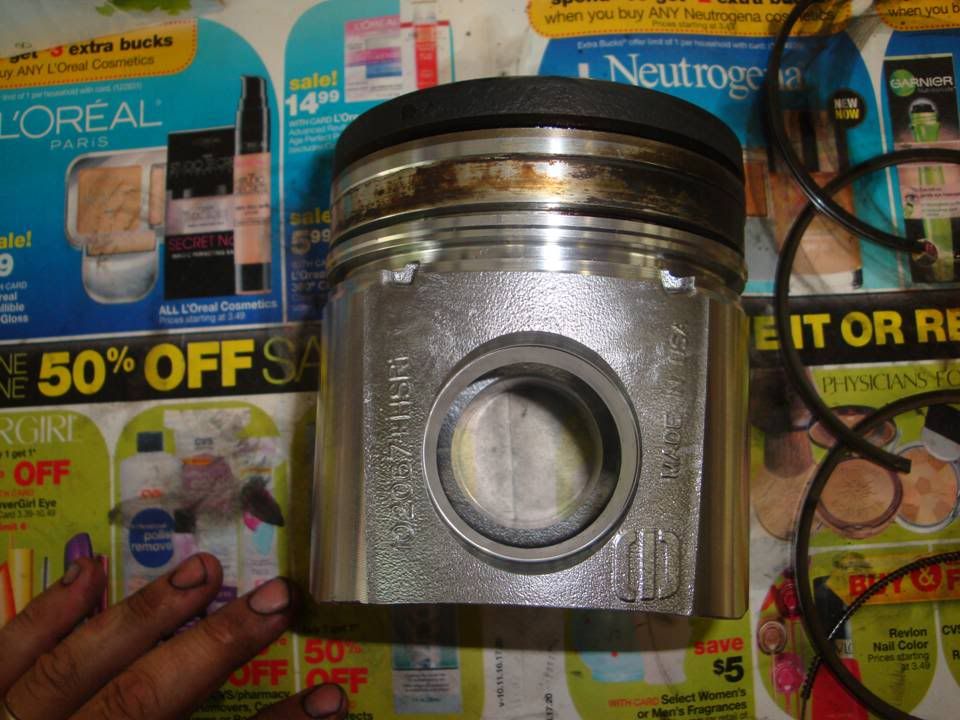
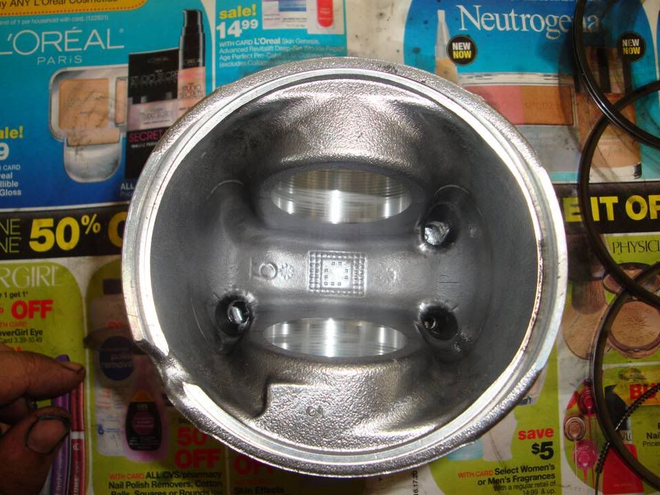
This is how they looked when they came out of the motor and before I sent them out.

Slide3-50.jpg


Slide11-2.jpg


Slide12-2.jpg


Slide1-77.jpg


Slide2-79.jpg


Slide3-53.jpg


Slide4-32.jpg


Slide5-18.jpg
 
Oh thats not good at all. I would almost say it looks like on there return trip they where packaged improperly and someone decided to play "hot potato" with your package as it was being loaded for shipping...

I hate when sh!t like that happens, especially something you have been waiting for.
 
OH man...Classic UPS!!!! I work in a metal plating shop(black Oxide) and UPS is VERY VERY bad about damaging the machined parts that get shipped in, OR my favorite!! Losing the packages!!! they managed to lose one package that was going 40 miles away!!! How did they do that??? Well atleast ur gonna maybe get new pistons!! or atleast a good discount on a new set!
 
Oh thats not good at all. I would almost say it looks like on there return trip they where packaged improperly and someone decided to play "hot potato" with your package as it was being loaded for shipping...

I hate when sh!t like that happens, especially something you have been waiting for.

Let's just say that I think there is more to the story that a shipping issue.

I have my beliefs about what really happened to them.
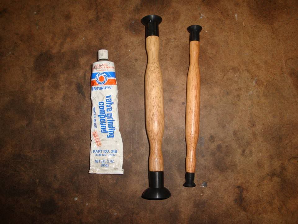
 
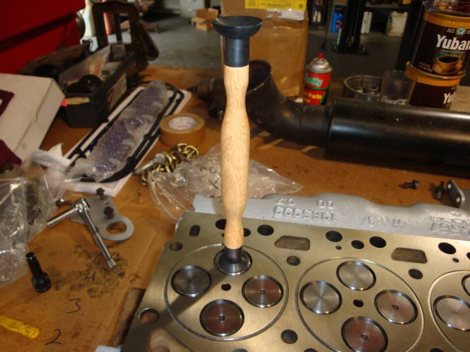
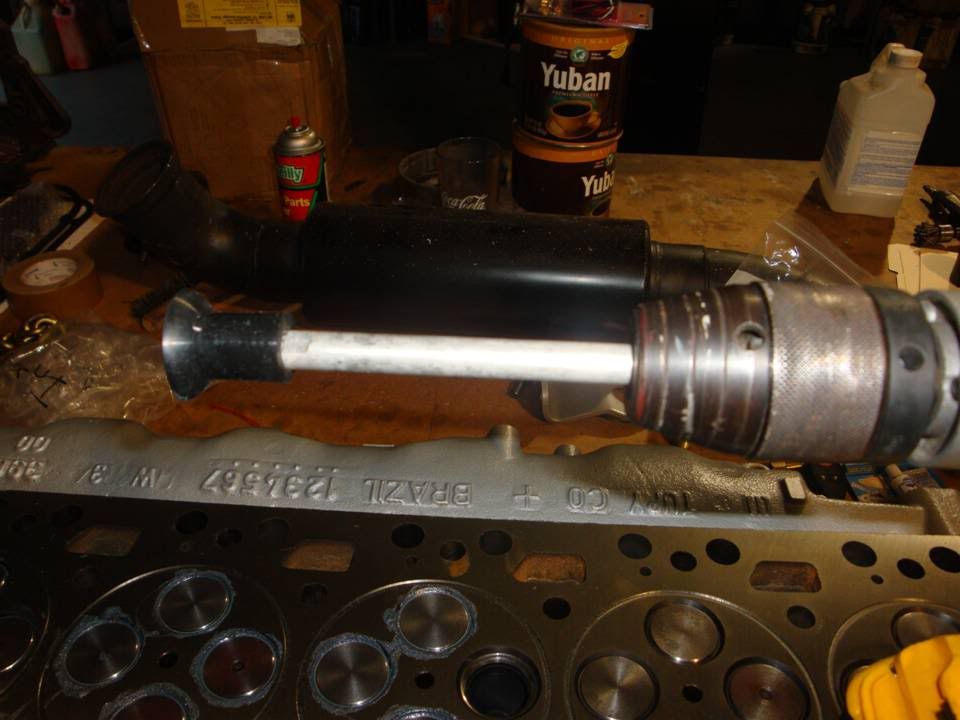
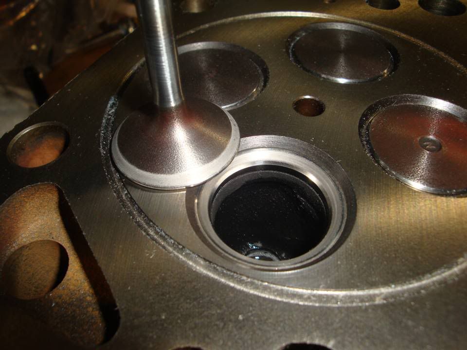
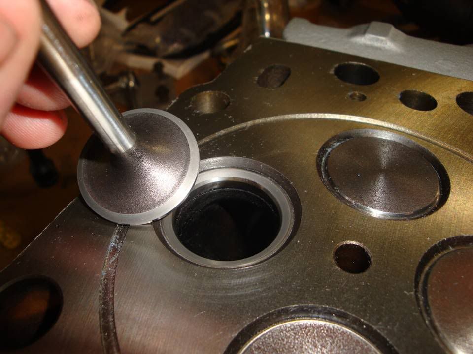
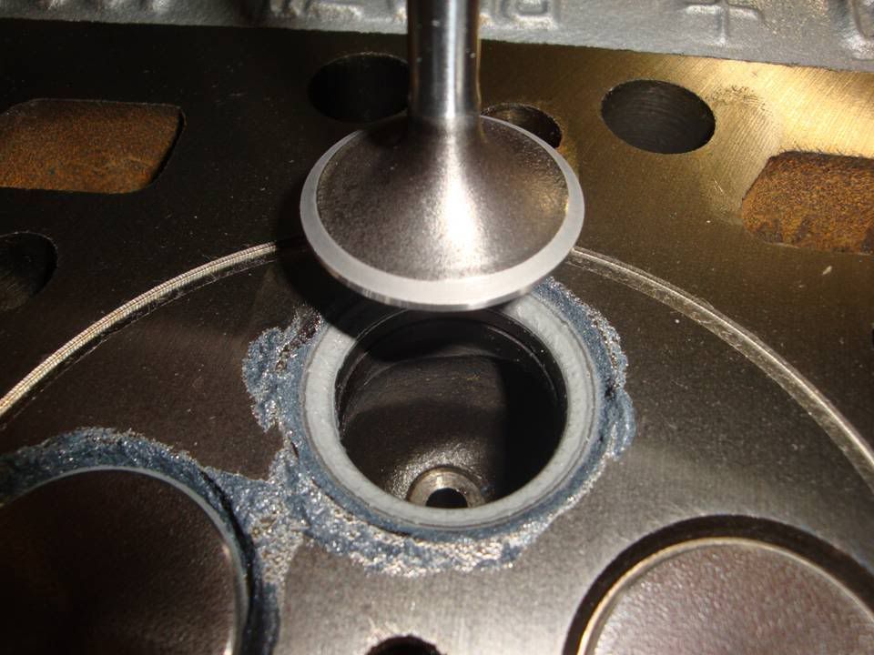
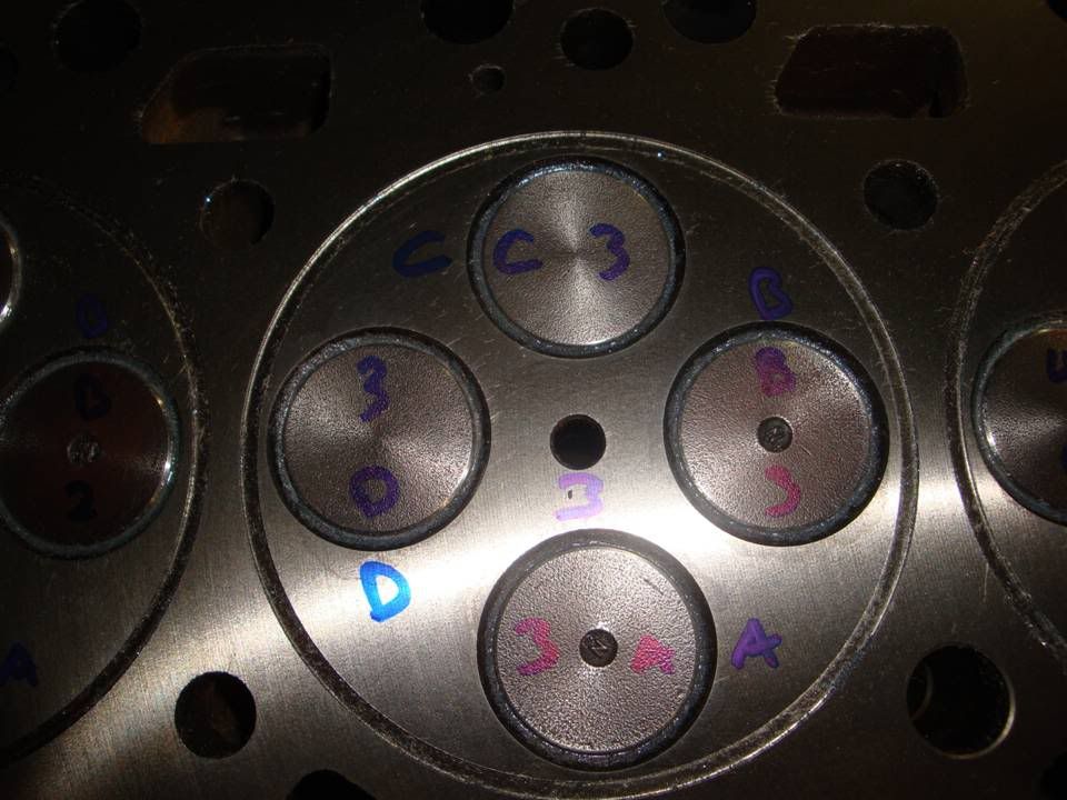
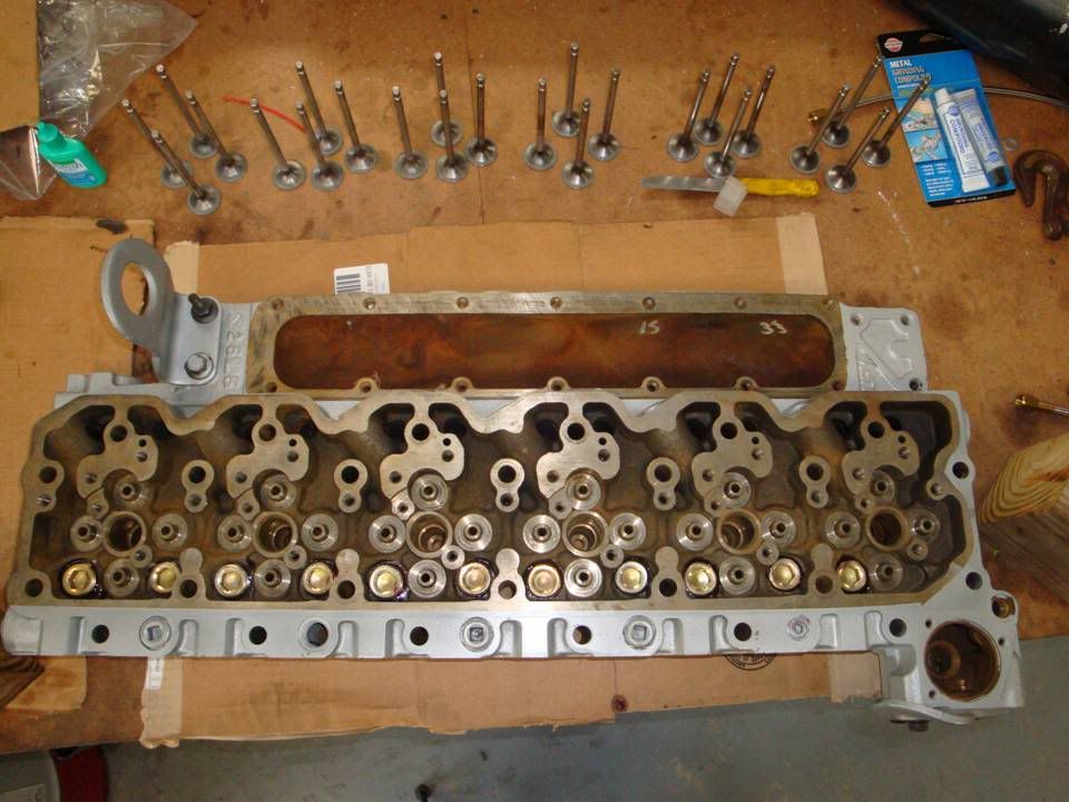
Got the valves all lapped today.

Gotta clean up the head tomorrow and then it'll go back together.

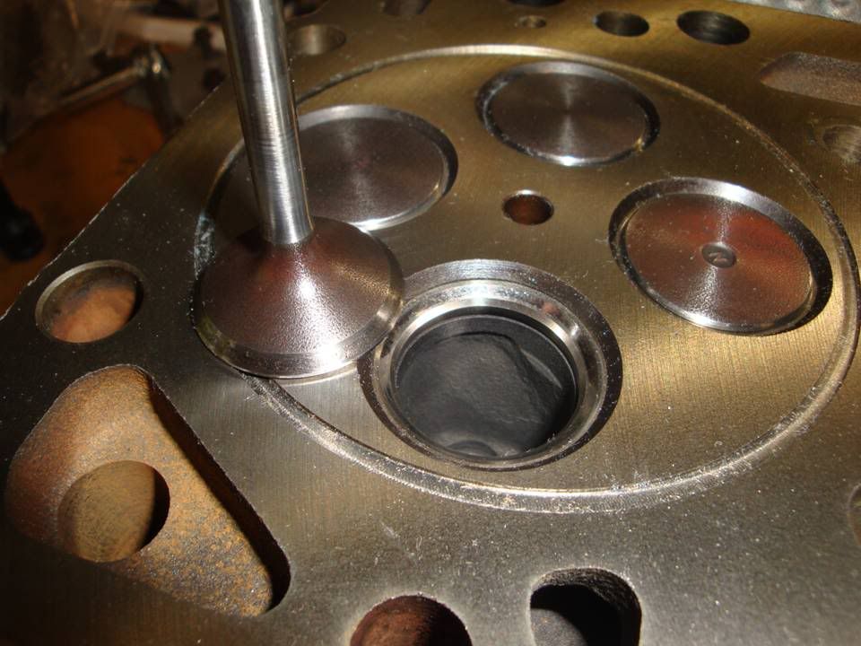
The valves came out MUCH better than what they were.

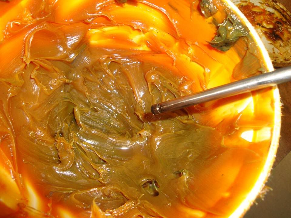
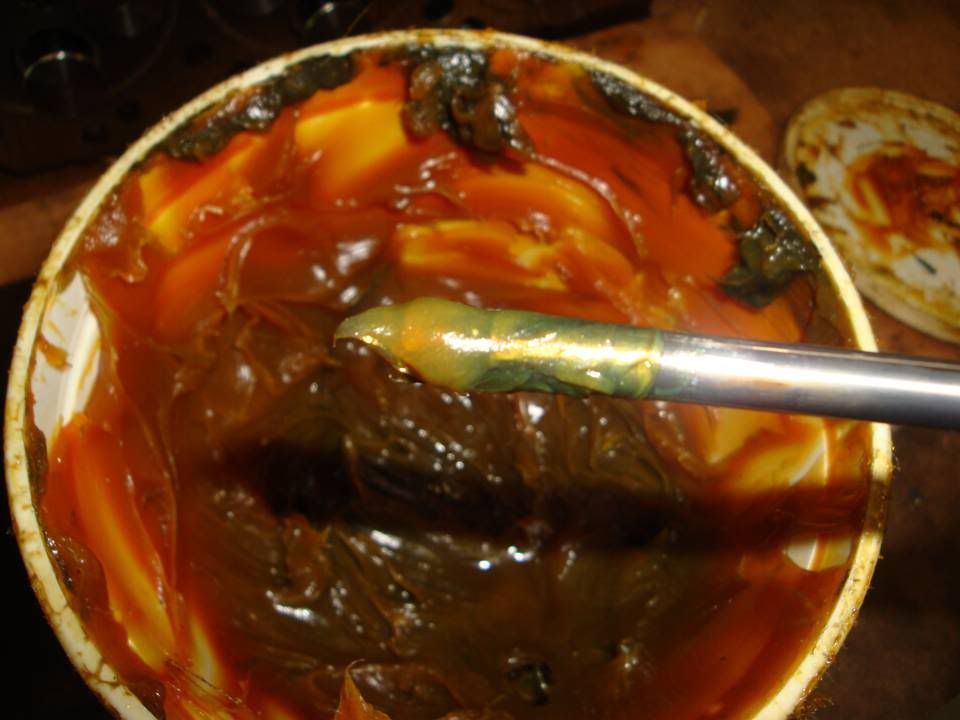
Some of the stuff you'll need.....

Slide1-101.jpg


Slide2-102.jpg


Slide3-74.jpg


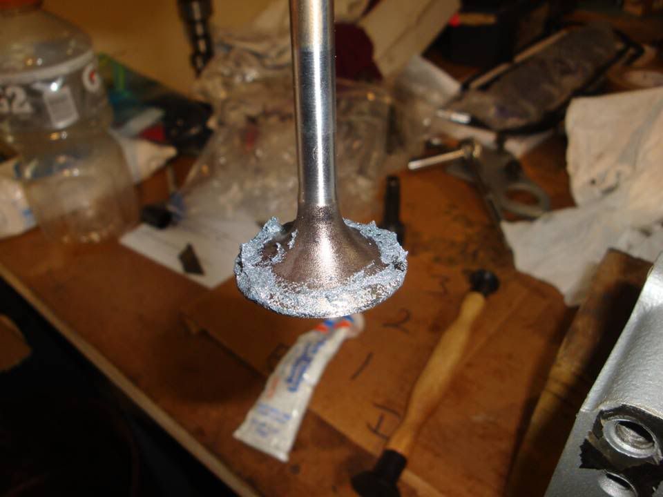
Before lapping.....

Slide4-46.jpg


Liberal coating of valve grinding compound.....

Slide5-32.jpg


Lapped to each valve seat.....

Slide6-21.jpg


Slide7-17.jpg


Slide8-14.jpg


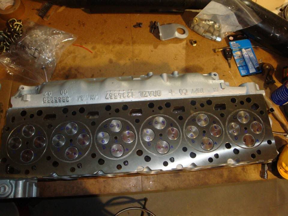
All valves done and marked for cleaning.

Slide9-12.jpg


Slide10-8.jpg
 
wow that's a wide contact area. is that to help reject heat?

Not necessarilly heat but cylinder pressure and boost. Don't forget, I run 72 lbs of boost and this motor is getting sprayed too.

I only cut them down far enough to remove the pits and high spots in the valves and seats.

Normally, on a gas motor you want 1/16 (intake) to 3/32 (exhaust) of valve to seat contact, but a gas motor usually has much stiffer springs and operates at higher RPM's.

Most diesel's don't have very stiff springs to begin with, so the narrow valve to seat contact area's don't work as well to seal.

The main consideration on these valves is maintaining the margin thickness and not cutting too deep into the seating surfaces that you reduce the margin thickness.

The other thing to look at while you're lapping them is to make sure the valve margin doesn't go below the valve seat.

Cutting the valves is kind of a balancing act between performace and longevity. Ideally, you want the valve to set contact area on a daily driven motor to be at a 45* angle. This gives you good longveity.

Now, on a performance motor or one that will see frequent tear downs and rebuilds, you might increase that angle to 50*, 52*, 55* to increase the airflow.
 
Are you finalizing them with a finer high quality compound like Clover 600 grit?
What are you using for interference angle? Any? Usually you see 1 deg difference between the valve and the seat.
Is there a dimension spec for the tops of the valve faces with respect to the head surface? This could have an effect on compression.

TM-5-6115-400-350096im.jpg
 
Last edited:
Nope, they are going in just like that.

If you look at the picture where the valve seat is still pretty clear, you can see the interference angle is still there.

The head will get cleaned up and the valves will go on the lathe with some Scotch Brite to clean them up, but that's it.
 
Little trick to verify your initial contact... Slide the valve in, hold the stem underneath, raise the valve and smack it back down into the seat a few. You will see the contact ring impression on the valve. It should be a little lower than the break where the margin starts on the valve. You don't want the initial seal to be all the way at that corner. If you don't get a distinct circle, you took too much.

I highly suggest you lap them with a finer grit compound. High finish will seal better. That stuff you're using is too coarse. Scotchbrite on a lathe after lapping? I wouldn't. Lapping is final. Just wipe them off.

The whole purpose of the interference angle is to not have to lap. So if you do lap you do it sparingly. Just enough to see the contact full circle.
 
Last edited:
Okay, here's today's work.

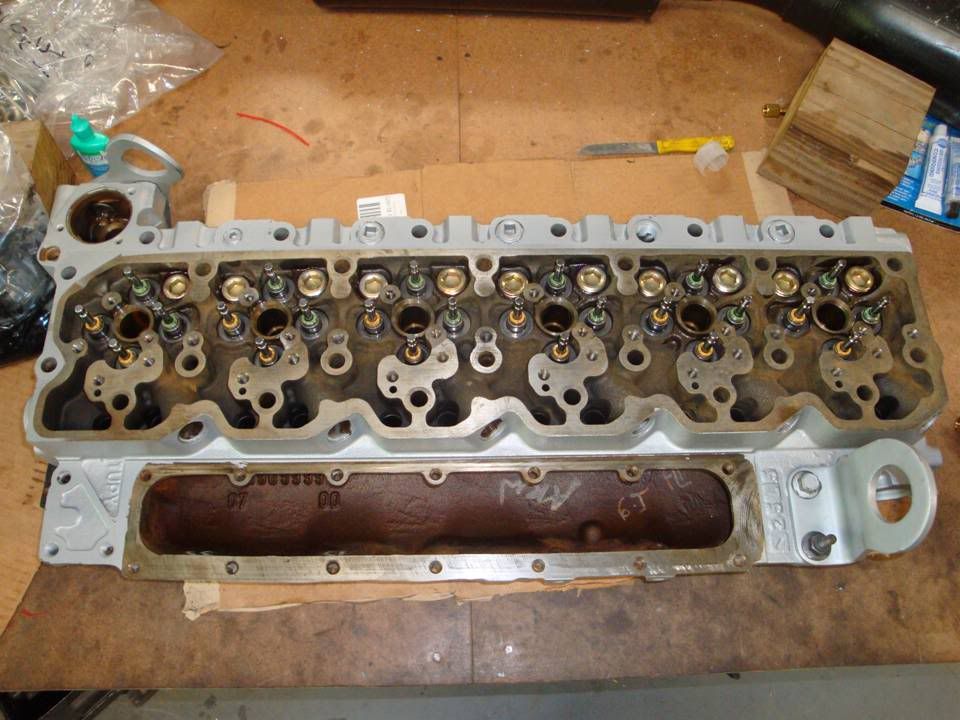
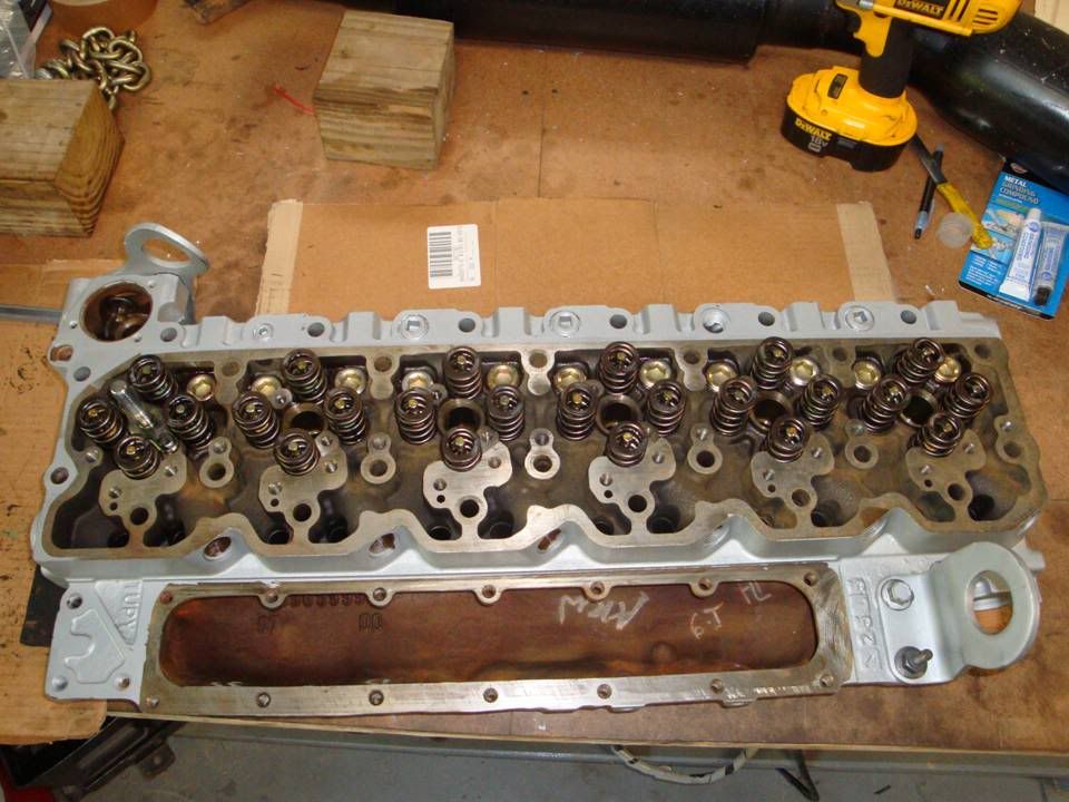
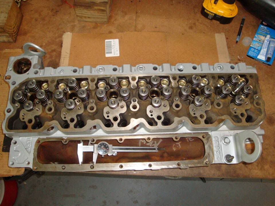
Got the head all cleaned up, the new plugs are in, got the valves polished up a bit and got the head put back together.

New pipe plugs installed instead of the freeze plugs.....

Slide1-102.jpg


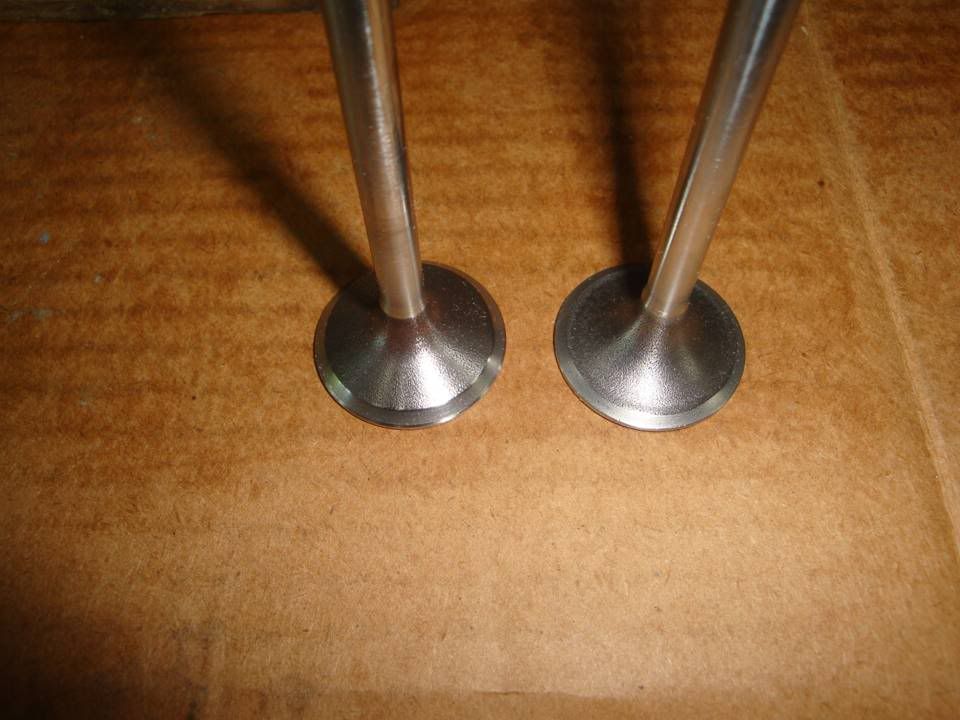
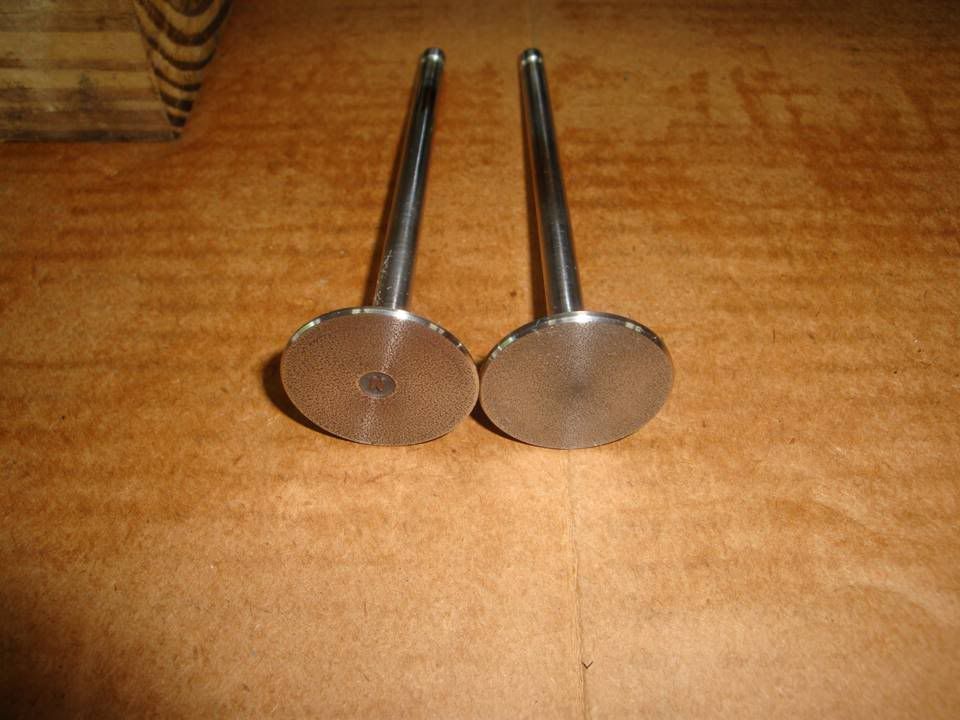
Intake and exhaust valves. The valves are the same size, but the design and seat angles are different.....

Slide2-103.jpg


Slide3-75.jpg


Grease the upper valve stem before inserting to lube the valve guides.....

Slide4-47.jpg


Slide5-33.jpg


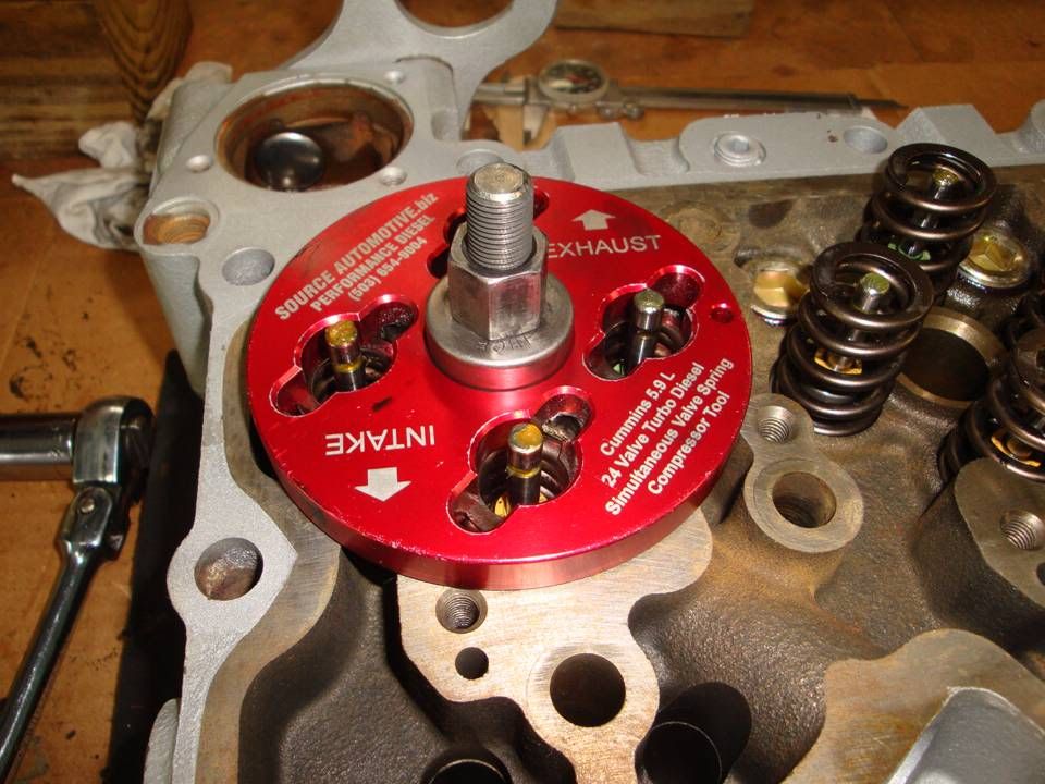
Time to assemble the head. Yellow is your intake valves, green is the exhaust.....

Slide6-22.jpg


Slide7-18.jpg


Slide8-15.jpg


Slide9-13.jpg
 
Man, that's purdy...where's that drool smiley...

I'm really getting into the details coming out in this thread. You doing all that work plus taking the time to share with us here is much appreciated...I know I'm looking forward to the updates...:thumbsup:
 
Man, that's purdy...where's that drool smiley...

I'm really getting into the details coming out in this thread. You doing all that work plus taking the time to share with us here is much appreciated...I know I'm looking forward to the updates...:thumbsup:

I look at it like this.....

How many folks actually live close enough to us to work on your truck?.....not many.

So, if I can post stuff up that possibly helps someone resolve a problem on their truck on their own or give them an idea of what they're in for with a project, that's cool with me.

Takes me all of 15 minutes each day to take and post pics.

:thumbsup:
 
This has to be one of the greatest threads ever. Rich you do great work thanks for sharing your build with us. I almost feel like I'm doing the build with your money.....):h The icing on the cake would be a live web cast when you go to fire her up....(hint) :D
 
This has to be one of the greatest threads ever. Rich you do great work thanks for sharing your build with us. I almost feel like I'm doing the build with your money.....):h The icing on the cake would be a live web cast when you go to fire her up....(hint) :D
It will certainly be on video.......good or bad.

):h
 
So, today was "Start Working on Sexying Things Up" Day.

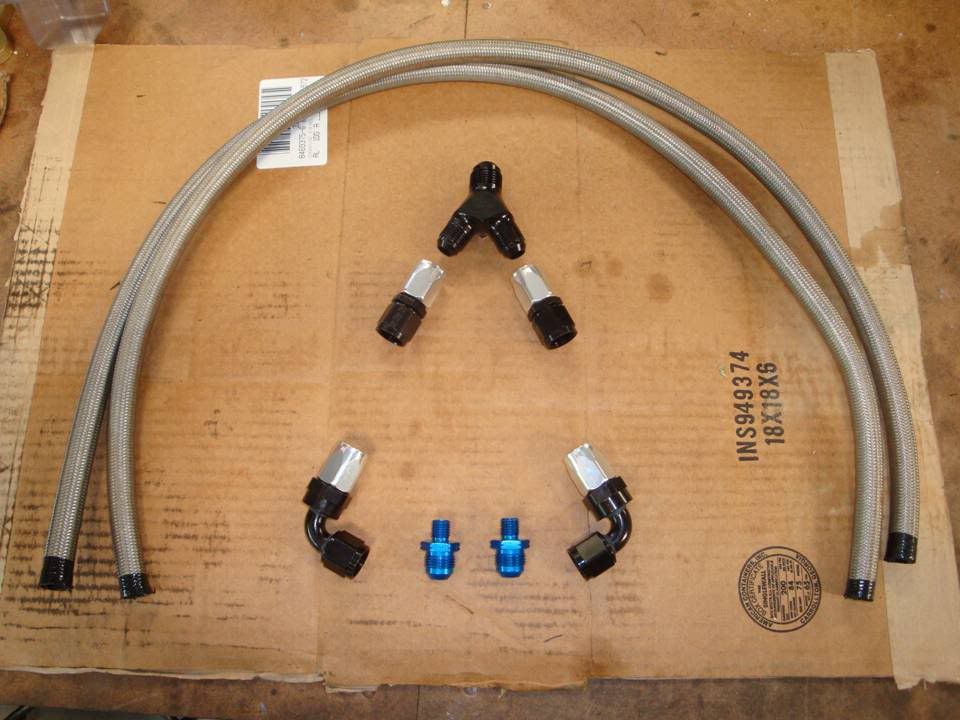
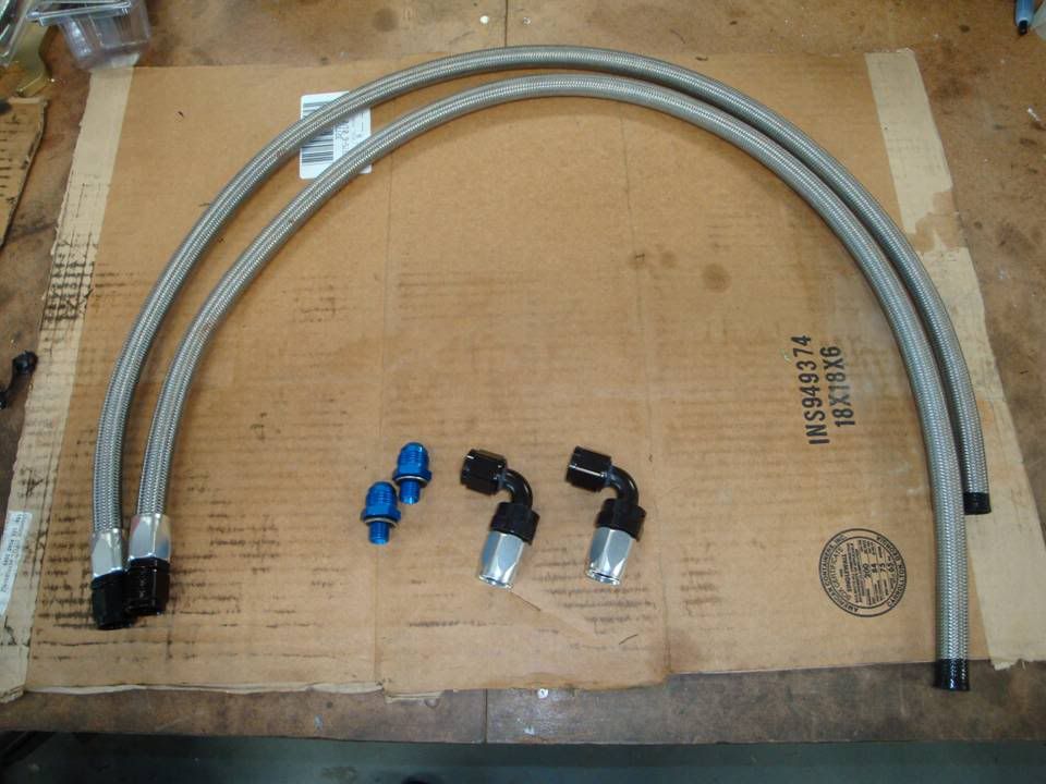
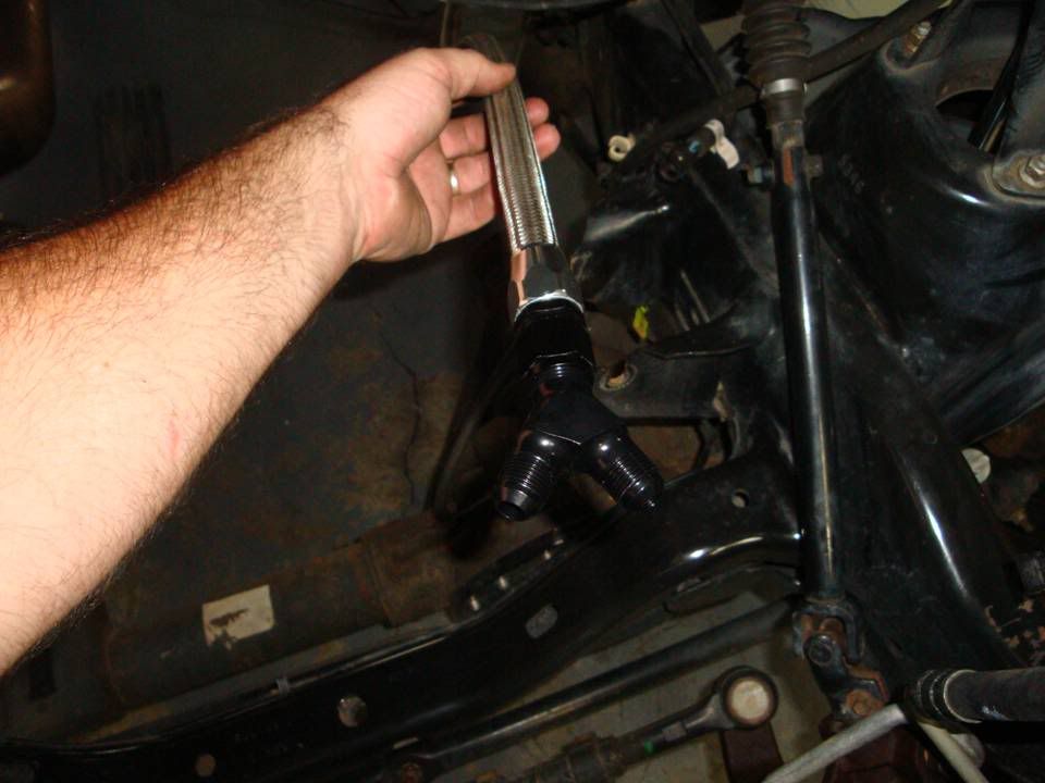
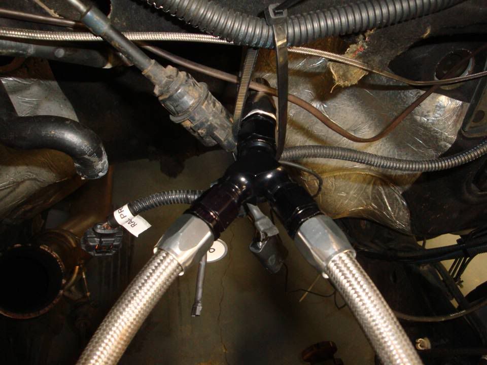
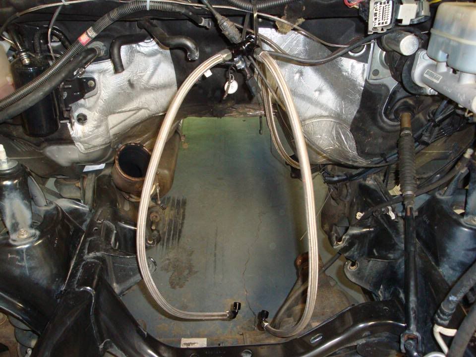
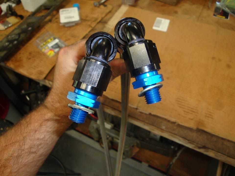
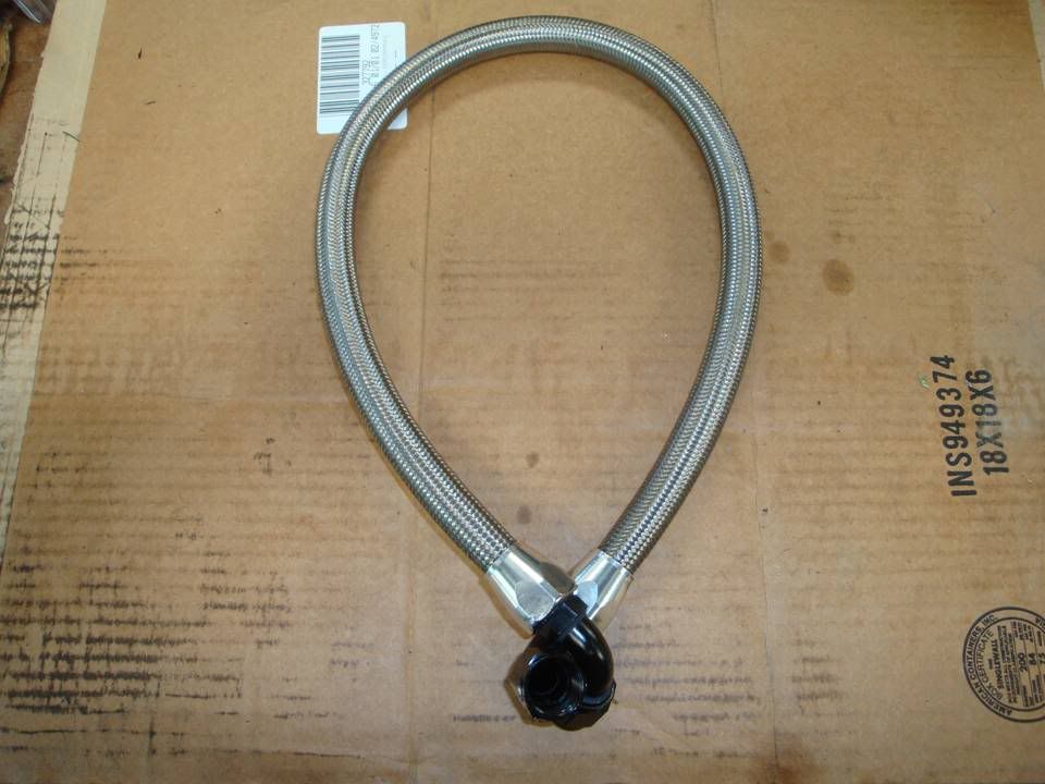
Got the fuel lines completed, for the most part. Will need to cut them to final length once I get the engine reassembled and can get the -8's to CP3's routed how I want them.

Once those were done, I started looking for all the ugly parts that I want cleaned up and painted or polished.

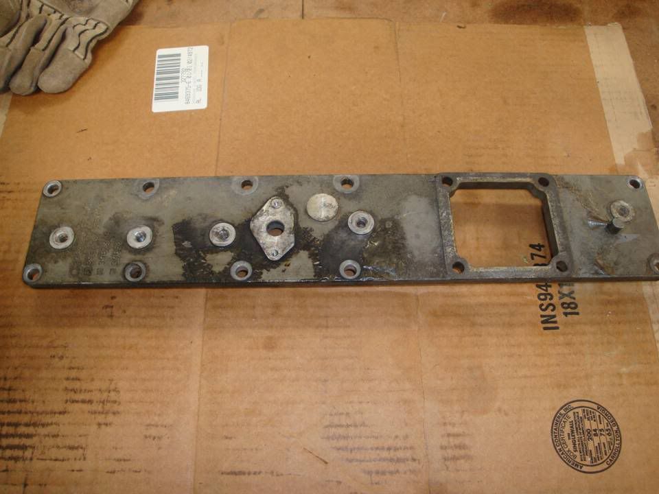
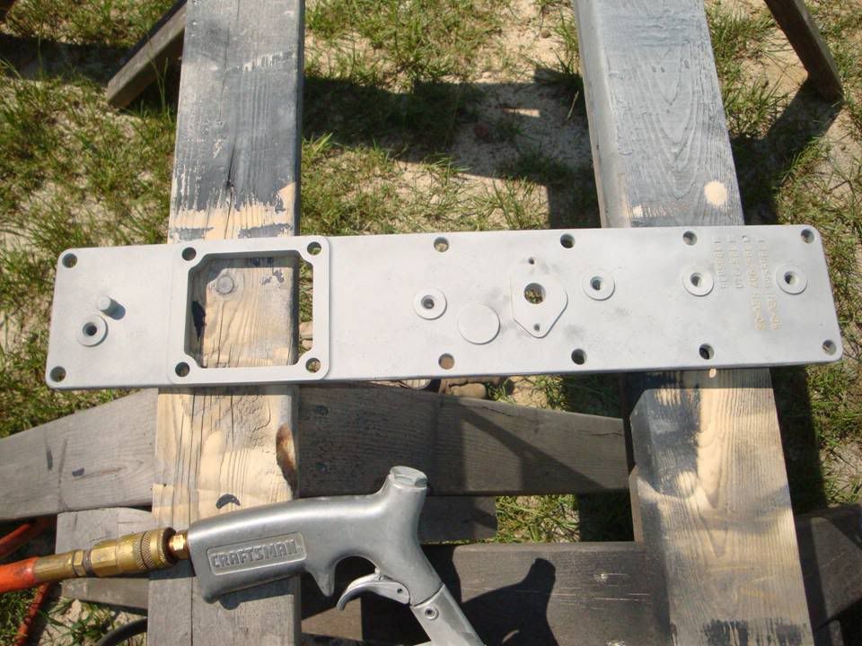
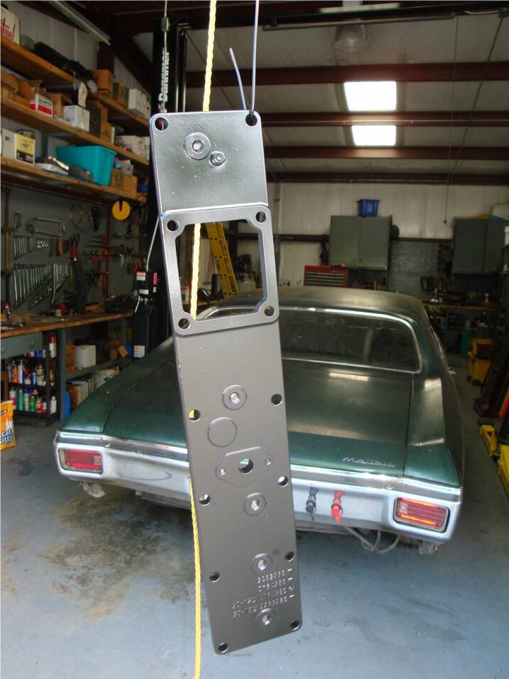
Started with the manifold cover. Blasted it and hit it with satin black.

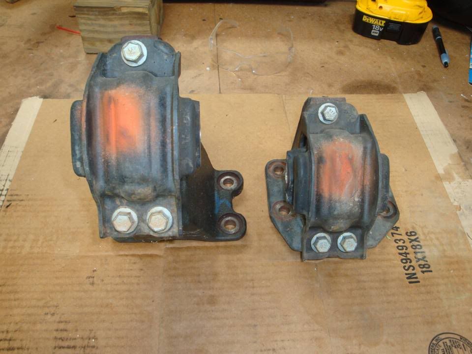
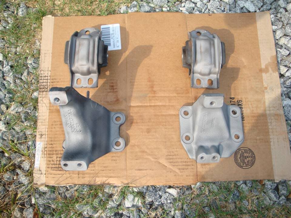
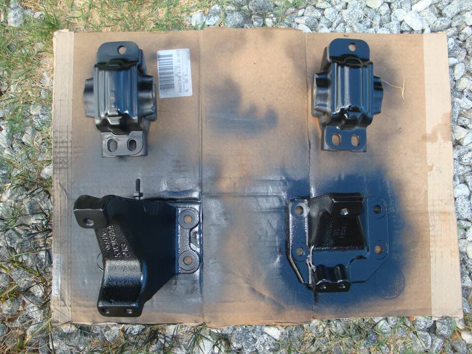
Next were the motor mounts. Those have been an eye sore for as long as I can remember. So, they got blasted and painted too.

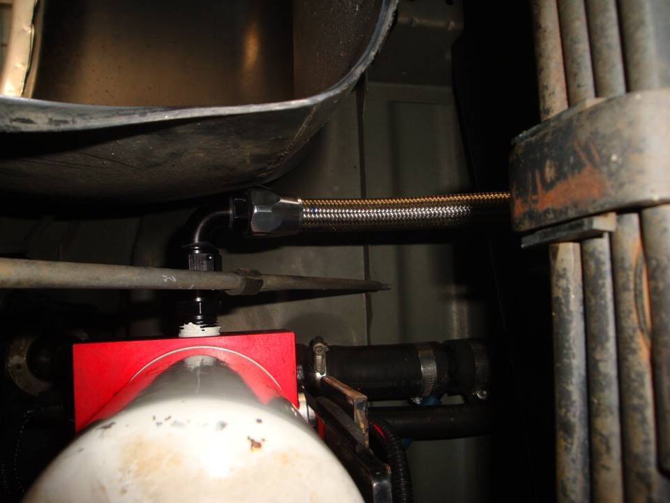
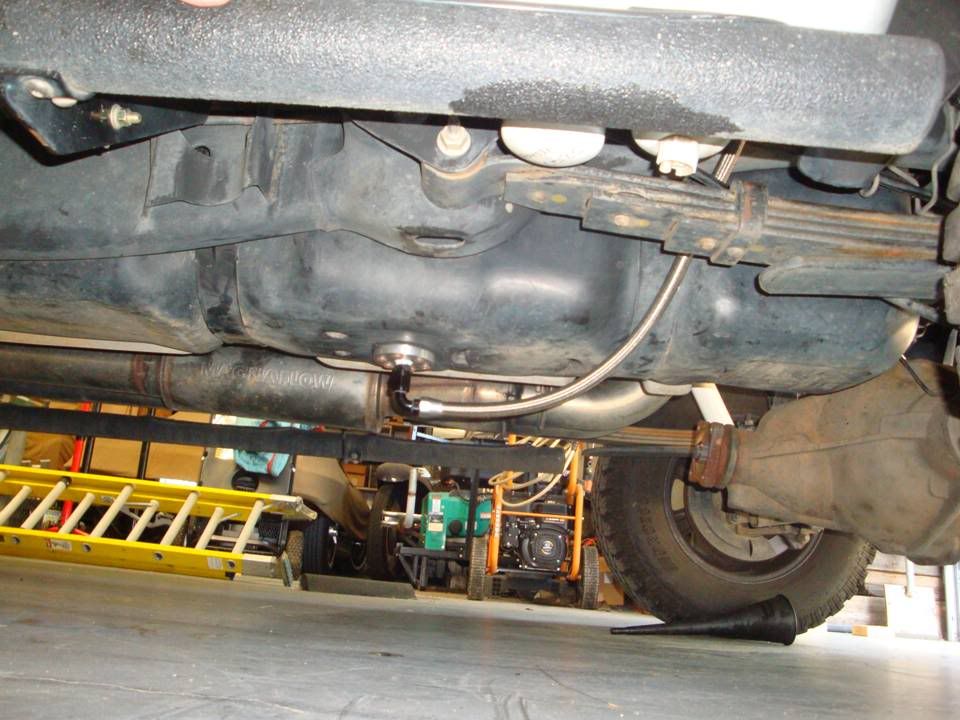
Here's the -10 fuel supply line to the FASS.....

Slide1-103.jpg


Slide2-104.jpg


Slide3-76.jpg


Here's where -10 ends and splits to -8's to the pumps. These are not yet cut to final length. the -10 will be shortened and the -8's will be cut to final length once the pumps are back on the motor.....

Slide4-48.jpg


Slide5-34.jpg


Slide6-23.jpg


Slide7-19.jpg


Slide8-16.jpg


Slide9-14.jpg


Now came the touching up the ugly parts.....

Slide10-9.jpg


Slide12-4.jpg


Slide11a.jpg


Slide11-7.jpg


Slide13-5.jpg


Slide14-3.jpg
 
Back
Top