Navigation
Install the app
How to install the app on iOS
Follow along with the video below to see how to install our site as a web app on your home screen.
Note: This feature may not be available in some browsers.
More options
-
Welcome to The Truck Stop! We see you haven't REGISTERED yet.
Your truck knowledge is missing!
- Registration is FREE , all we need is your birthday and email. (We don't share ANY data with ANYONE)
- We have tons of knowledge here for your diesel truck!
- Post your own topics and reply to existing threads to help others out!
- NO ADS! The site is fully functional and ad free!
Problems registering? Click here to contact us!
Already registered, but need a PASSWORD RESET? CLICK HERE TO RESET YOUR PASSWORD!
You are using an out of date browser. It may not display this or other websites correctly.
You should upgrade or use an alternative browser.
You should upgrade or use an alternative browser.
Pseudo-Resto 96 K-1500…Um, when was this a good idea?
- Thread starter Paveltolz
- Start date
Paveltolz
Доверяй, но проверяй
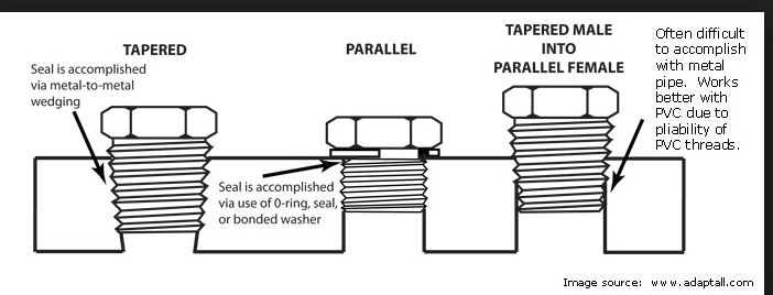
Thanks Mike. That should go in the Parts Sticky for all forums to help the ignorant such as myself.NPS is National Pipe straight. In other words same thread but not tapered.
Sometimes referred to as parallel.
View attachment 46270
I did find an extra 3/8 inverted flare fitting (two in fact if anyone else wants to ignore my lesson learned of just leaving things alone) and the answer is no, it wouldn't work. Well, not without a hammer and room to swing it.
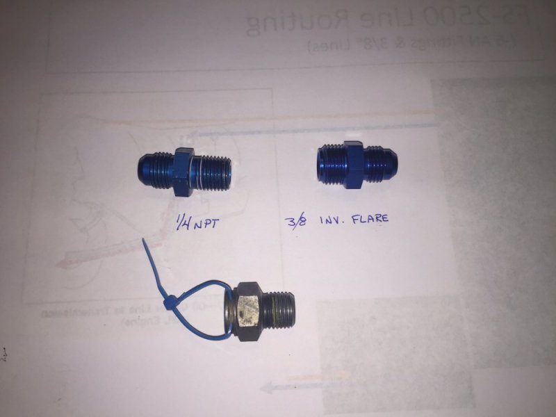
Bottom fitting is the OEM piece with the zip tie to ID that it is for the Input Line/Port.
I was just joking. Mine took 1/4"npt.
Paveltolz
Доверяй, но проверяй
I know Amigo, and I got quite the chuckle out of it. I also figure that pointing out why the statement was really a joke would be a good thing. Trust me, with the way my projects go, a sense of humor is appreciated...like 150 PSI potato canons. Brought back memories of the ones we'd make only using tennis ball cans for the barrels, aerosol cans for the combustion champers and lighter fluid for propellant....I was just joking. Mine took 1/4"npt.
Paveltolz
Доверяй, но проверяй
Transmission lines done. I needed to run a 1/4" -18 Tap, with the vacuum cleaner sucking transmission fluid out of the hole, into the pressure side to clean the threads. I didn't use any t-handle or anything, just turned it in by hand and back out once.
I never even felt a hitch or any resistance. Did about three turns and backed it out with the vac. running the whole time and the issue was solved.
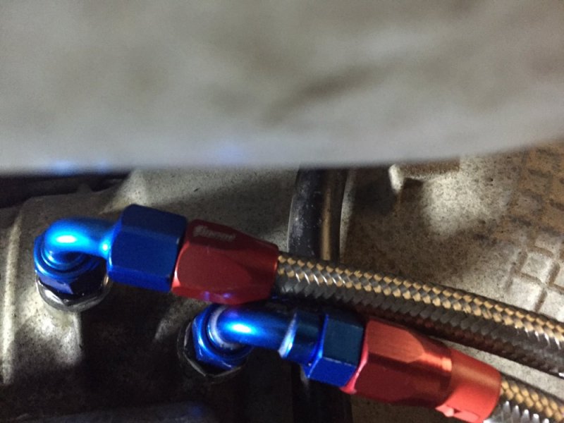
I was going to use the red NPT fitting but decided to use the two black 'transmission adapter fittings' with the aluminum 'bonded seal'/crush washers.
Lines are in and I've used quite a few zip ties around heater hose used to protect the rubbing areas. I'll do the same with the Oil Cooler lines tomorrow. Tempted to do those over as they are about 2" too long but they're made differently and I'm not going through this again when they are just fine. Just need to be better routed and protected. Thankfully there's no chaffing on them so the old adage of 'don't let perfection get in the way of good enough' is going to apply to that side.
I'm going to revisit the way they line up at the transmission. Not entirely liking how they make contact and they don't have to b touching.

Paveltolz
Доверяй, но проверяй
Got up early and endured yet another one of our horrible sunrises.


I swear they get worse by the day.
After harvesting weeds I've ignored all summer long I was finally able to get at the lines and get them positioned at the transmission a bit more to my liking.
Before
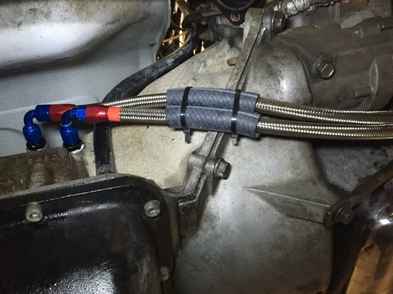
...and After
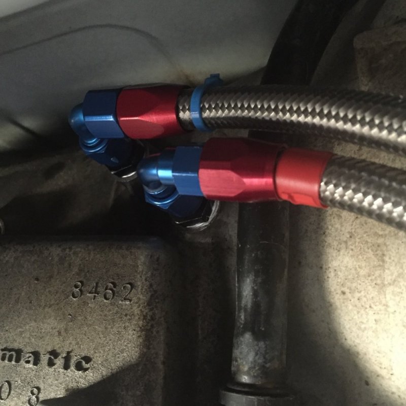
Then it was time to secure and protect them and other hoses/wires that may come in contact. I had done this last night but had to cut all the zip ties to get the lines positioned at the transmission.
I found some wire/hose clamps and my last usable piece of heat blanket then went to work using the 5/8th radiator hose here and there as protection as well.
Heat shielding over 5/8" hose at the bell housing vs. hose only to protect from the cross over exhaust heat.
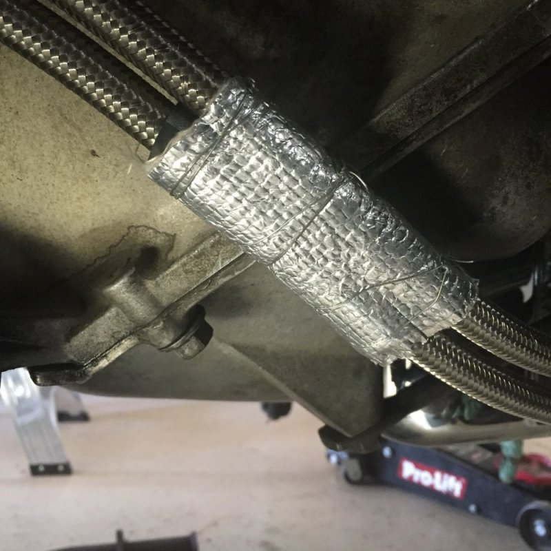
Hose Clamps reduced the need for four other pieces of 5/8 hose used last night.
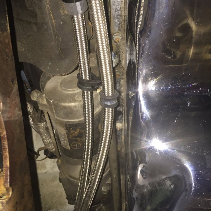
Wrapped the diagonal support with 5/8" hose and added more here and there to protect specific components like radiator lines, ABS etc.
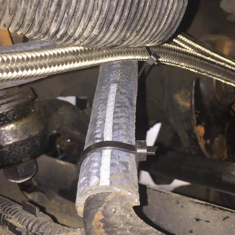
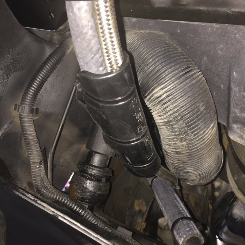
I'll add more 5/8" hose to the lines at the Aux. Cooler when the splash guard goes back on.
Before wrapping up for the day, I put Red, Yellow and Blue Zipties at the connectors for the lines running from the Trans to the Aux Cooler input (Red for HOT [already had red electricians tape at the Transmission), Aux Cooler output to the lower Radiator input (Yellow for not as hot) and Blue from the Radiator's output back to the transmission (Blue for Cool-ish).
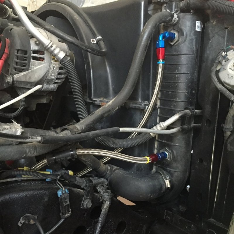
So, with another day of anal-retentiveness complete, I'm wrapping up to play with my new grandson. Priorities, right people?


I swear they get worse by the day.
After harvesting weeds I've ignored all summer long I was finally able to get at the lines and get them positioned at the transmission a bit more to my liking.
Before

...and After

Then it was time to secure and protect them and other hoses/wires that may come in contact. I had done this last night but had to cut all the zip ties to get the lines positioned at the transmission.
I found some wire/hose clamps and my last usable piece of heat blanket then went to work using the 5/8th radiator hose here and there as protection as well.
Heat shielding over 5/8" hose at the bell housing vs. hose only to protect from the cross over exhaust heat.

Hose Clamps reduced the need for four other pieces of 5/8 hose used last night.

Wrapped the diagonal support with 5/8" hose and added more here and there to protect specific components like radiator lines, ABS etc.


I'll add more 5/8" hose to the lines at the Aux. Cooler when the splash guard goes back on.
Before wrapping up for the day, I put Red, Yellow and Blue Zipties at the connectors for the lines running from the Trans to the Aux Cooler input (Red for HOT [already had red electricians tape at the Transmission), Aux Cooler output to the lower Radiator input (Yellow for not as hot) and Blue from the Radiator's output back to the transmission (Blue for Cool-ish).

So, with another day of anal-retentiveness complete, I'm wrapping up to play with my new grandson. Priorities, right people?
Attachments
NVW
Well-Known Member
Wouldn't the top fitting at the rad be the inlet?
Paveltolz
Доверяй, но проверяй
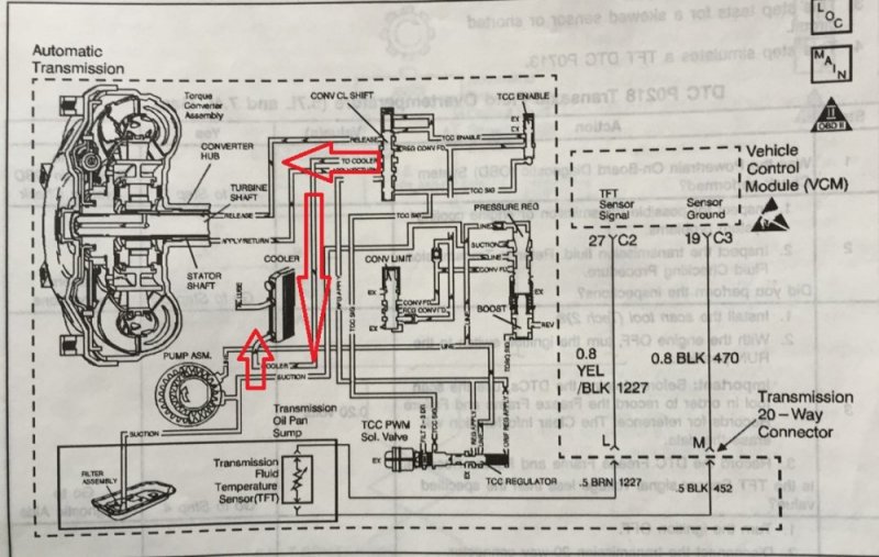
That's the logical way to look at it but the GM Manuals, Gearz Transmission Shop, Transgo Transmission of CA, and other's here all indicated that the lower port on the transmission and the Radiator is the Pressure Side and the upper ports are the returns. Chasing the lines, they run from the lower trans port, out to the Aux cooler (where equipped), out to the lower radiator port, and out from the upper radiator port and back to the upper port on the transmission.Wouldn't the top fitting at the rad be the inlet?
It's hard to see in this low Res scan of the transmission but you can see the Cooler in the middle and I've tried to highlight the Fluid's path (MS Paint SUCKS) and the line indicates the feed from the transmission runs to the "Cooler," which is in the radiator for this illustration, and enters in at the lower side. Upper goes out to "LUBE."
NVW
Well-Known Member
Good to know, thanks Paul.
btfarm
America First!
Nice job on the install.
Did you keep aux cooler?
Will L.
Well-Known Member
It goes into the lower one because it can push out any air bubbles. If it went in the top and "fell down" it could allow air intrusion and aeration. All forms of heat exchangers operate that way. Just like coolant in the radiator.
Looking good Paul!
Looking good Paul!
Paveltolz
Доверяй, но проверяй
Yes I did. I've been 4 wheeling in some slow, steep terrain and noticed the Trans Temp climb. Not a lot but some so better safe than sorry.Did you keep aux cooler?
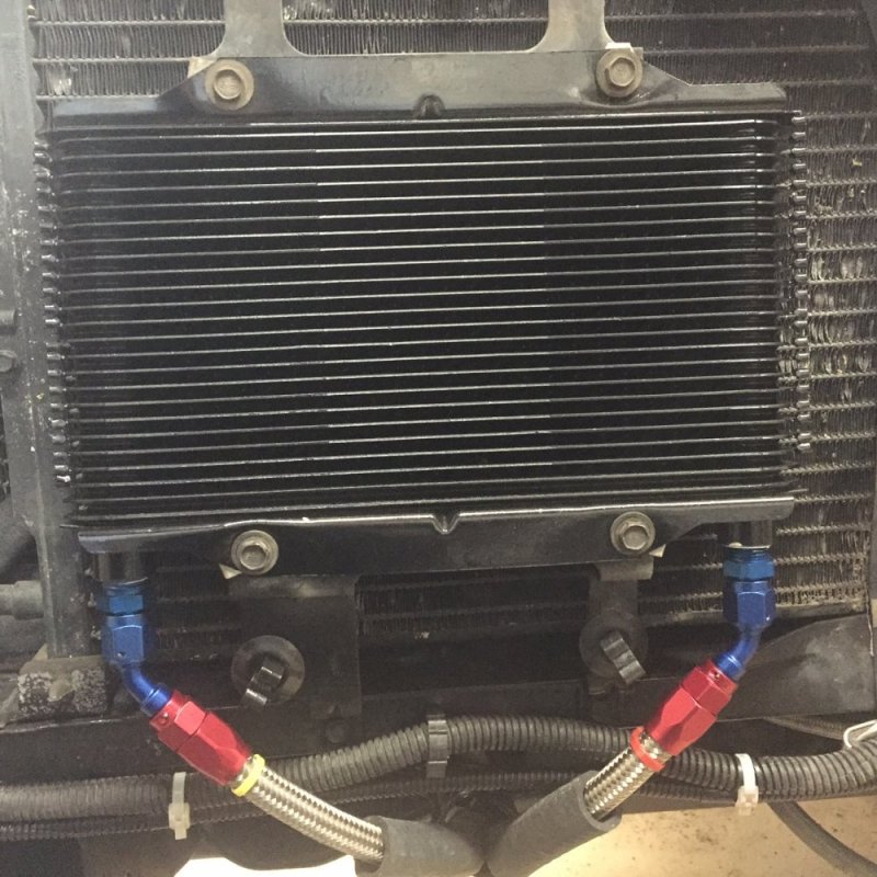
Here it is looking pretty much like the mock up save for the bolts are all in place, the Red and Yellow zip tie identifiers on the lines and some 5/8" hose ready to get secured if needed when the splash plat goes back in.
Now it makes perfect sense. Thanks Will, it is always good to know the reason or method to the madness rather than, "It's in the instructions." The drawings in the GM manuals don't always line up to what's in the garage either.It goes into the lower one because it can push out any air bubbles. If it went in the top and "fell down" it could allow air intrusion and aeration. All forms of heat exchangers operate that way. Just like coolant in the radiator. Looking good Paul!
Chevypoor
Active Member
Looks good, nice job!
DieselSlug
Well-Known Member
Nice to see you still going on her!
Paveltolz
Доверяй, но проверяй
Been on the road again with work so no real progress of late. I did get the turn signal wiring up front straightened out before leaving though.
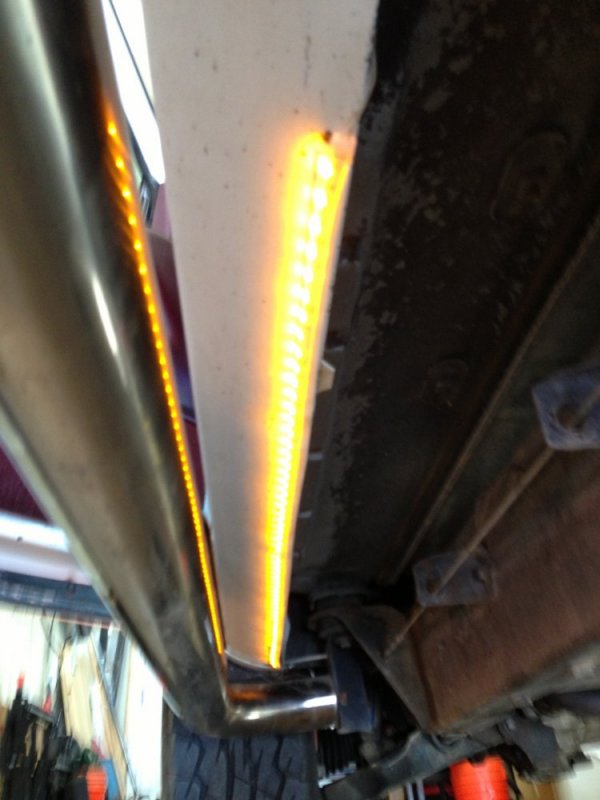
Some time ago I connected 36” amber LED strips under the rocker panels to the turn signal circuit.
I didn’t want to use T-Splices given exposure to weather so I found a workable alternative using some three-way splices from Real. Designed for home wiring, I filled them with NoLox and spliced away.
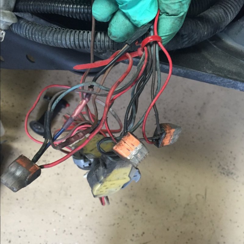
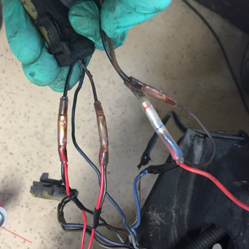
When I found out about the Wyteck splices I decided to re do them. I didn’t even have to cut the wires as I simply crushed the old splices and the wires backed out easy peasy. Cleaned the Nolox off, crimped on the new connectors, hit them with the heat gun to shrink things up and done. To protect the wires running though the fender I wrapped those in some wire loom. Now it all just has to wait for re-assembly and its ready to go.
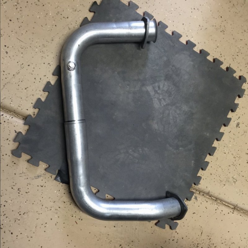
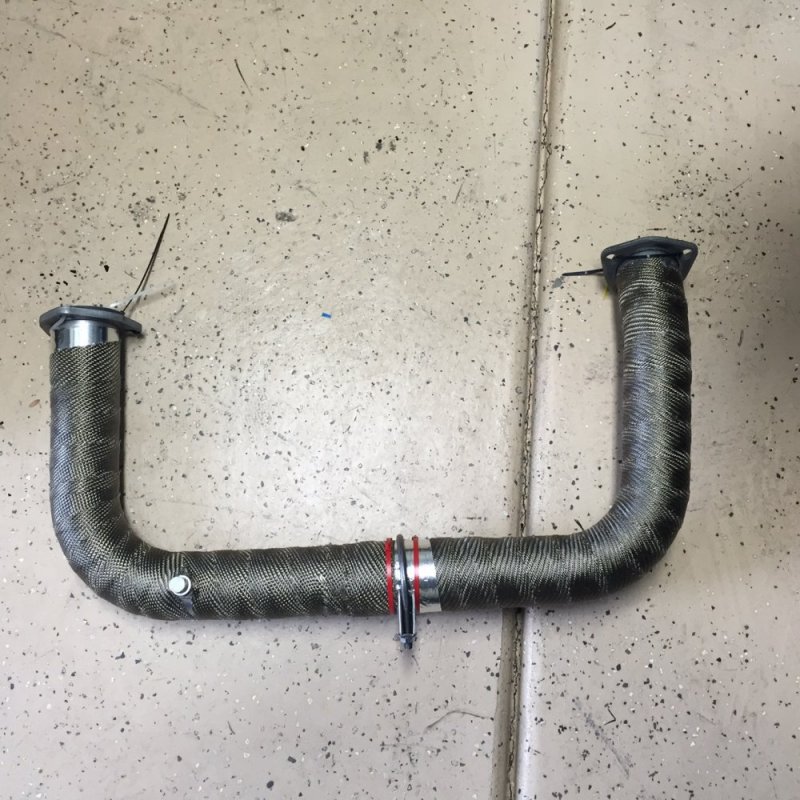
I also got a new cross-over pipe so decided to take some time to wrap it up. I started at both ends and worked to the middle. I’ll finish it off once it is on the truck and the lengths and angles are finalized.
Little by little.
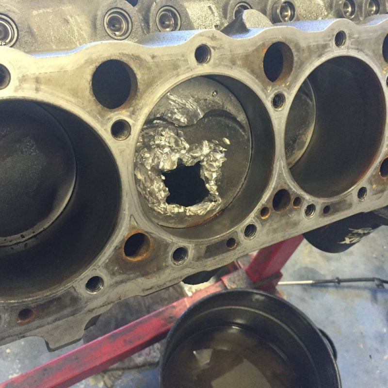
I stopped in to see Bill Heath on the last trip. He showed me what happens when an expensive part fails (valve) and gets stuck between the heads and the piston…not pretty. 350 Chevy gas race motor. Ouch!
Some time ago I connected 36” amber LED strips under the rocker panels to the turn signal circuit.

I didn’t want to use T-Splices given exposure to weather so I found a workable alternative using some three-way splices from Real. Designed for home wiring, I filled them with NoLox and spliced away.

When I found out about the Wyteck splices I decided to re do them. I didn’t even have to cut the wires as I simply crushed the old splices and the wires backed out easy peasy. Cleaned the Nolox off, crimped on the new connectors, hit them with the heat gun to shrink things up and done. To protect the wires running though the fender I wrapped those in some wire loom. Now it all just has to wait for re-assembly and its ready to go.

I also got a new cross-over pipe so decided to take some time to wrap it up. I started at both ends and worked to the middle. I’ll finish it off once it is on the truck and the lengths and angles are finalized.


Little by little.
I stopped in to see Bill Heath on the last trip. He showed me what happens when an expensive part fails (valve) and gets stuck between the heads and the piston…not pretty. 350 Chevy gas race motor. Ouch!

SS FORCE
Active Member
Any progress is progress right? I hate to say this, and correct me if I'm wrong, but due to your lift wont you need to lengthen the driver side of the crossover to fit around the front driveshaft? I know on mine I had to but it was the bigger lift.
Paveltolz
Доверяй, но проверяй
No issues with the cross over and the lift when I had it in as it was torsion bar only with those lovely extended upper control arms. The new lift with either BDS kit (desired originally but they got rid of the re-designed steering knuckles and went with a familiar looking redesigned upper control arm...) or Tough Country and dropping the differential may be a different story though. One of the things I'd have to talk to the shop about.
Chevypoor
Active Member
Lookin' good. X2 on progress- any is a good thing. Ouch on the 350!
Paveltolz
Доверяй, но проверяй
Another small project. OPS and Turbo Oil Feed assembly.
This engine block doesn’t have the Turbo Oil Feed port at the front of the motor nor the OPS port in the valley. Rather, there’s an oil port at the back of the motor directly under the Glow Plug Relay that has to pull double duty. The oil pressure gauge sender (after market) is attached to the port on the D/S of the block.
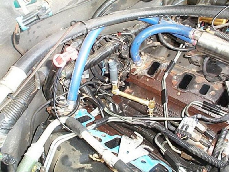
In 2012, while the motor was still out of the truck, I had created an assembly to handle the OPS and Turbo Feed that was inspired by TurbineDoc’s OPS relocation project.
Here's a shot of Doc's
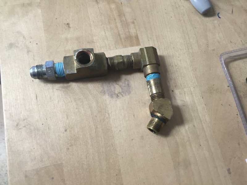
My old set up
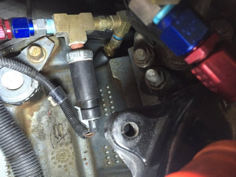
It seemed to have worked fine but I was never really all that pleased with the end result. It was a bit loose too as it got moved a bit during installation of the motor. Given the leverage easily applied to it, the 45* piece at the block was pretty much a swivel and I suspected it was responsible for a bit of the oil leaking I was having. Removing the assembly and inspecting proved it was oil free at every juncture to include the block.
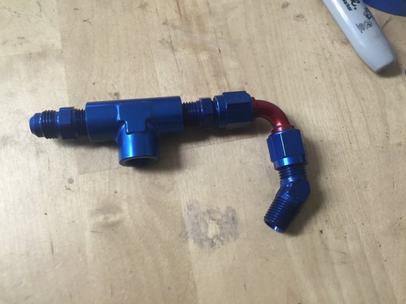
I had wanted to use a single 6 AN fitting ported like the fuel pressure fitting used in that re-do project but couldn’t source one tapped 1/4 NPT for the OPS. So, I cobble one up with the results having one less part as the brass set up. 45* 1/4 NPT to 6AN Male, 90* 6AN double female, 6AN back to 1/4 NPT fittings x2; 1/4 NPT “T-Block”.
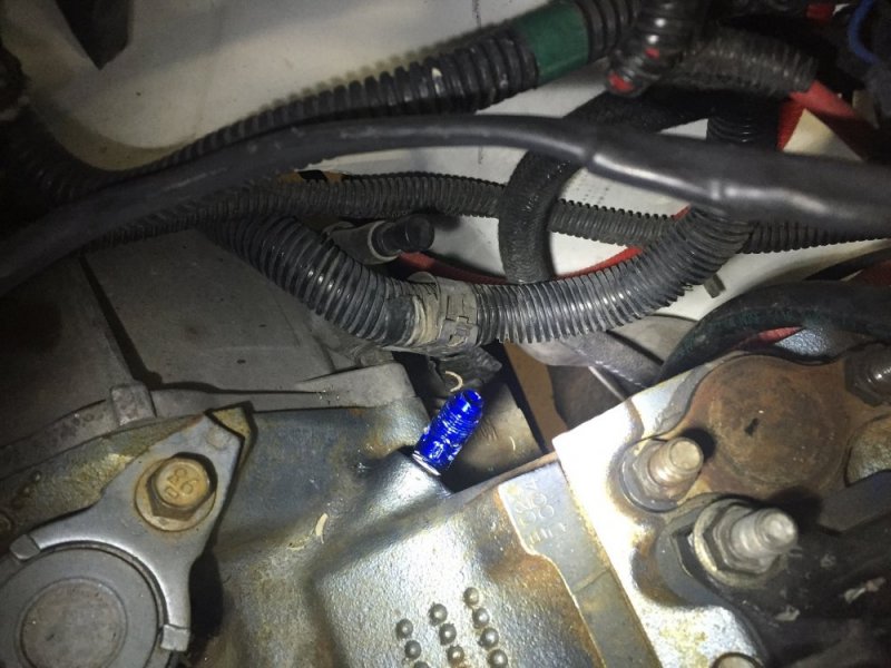
Removal of the old assembly and Installation of the new was straight forward. After disconnecting the fuel return hose to give access to the fitting at the block as well as the Glow Plug Relay for more access clearance; removed the Turbo Oil feed line, OPS, Brass T, 1” short pipe, 90* fitting with its 1” short pipe and then the 45* fitting at the block. Then reverse it with the new parts.
45* Fitting at the block.There was no way to keep the 45* fitting pretty given the close quarters in there so it got nicked up…Life.
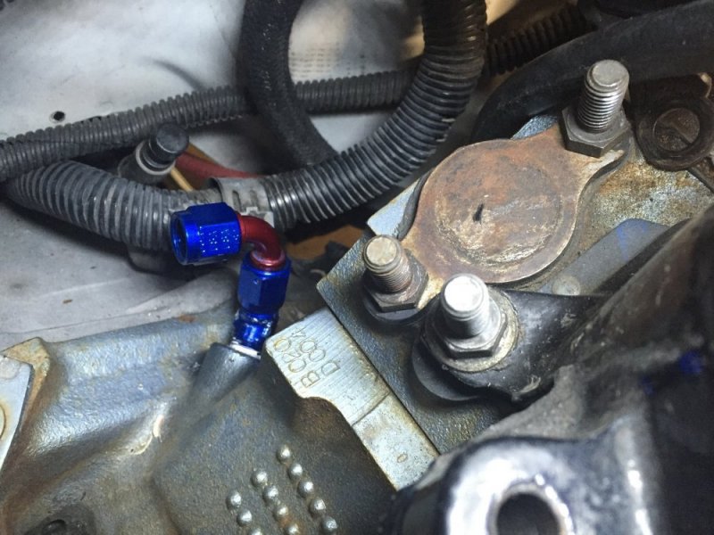
90* attached to the 45*
T-Block with the two 1/4 NPT-6AN fittings pre installed.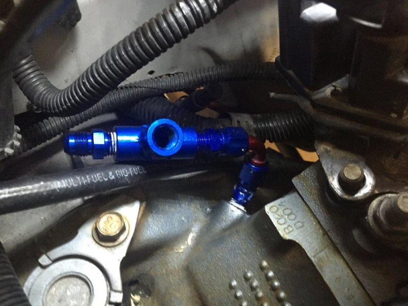
Fuel Return Line, GP Relay and Turbo Oil Feed Line attached (yes, I remembered to put the two 15mm nuts back on the GP Relay).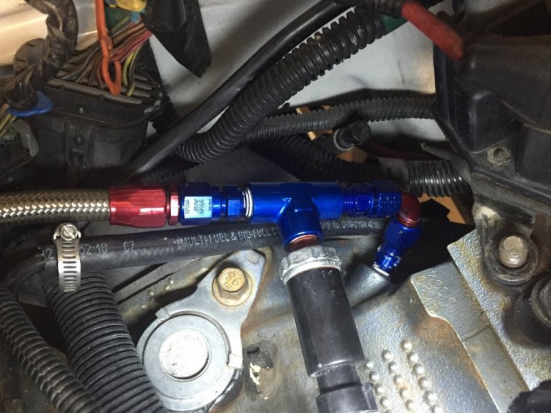
I guess I'll need to finish the firewall next....
This engine block doesn’t have the Turbo Oil Feed port at the front of the motor nor the OPS port in the valley. Rather, there’s an oil port at the back of the motor directly under the Glow Plug Relay that has to pull double duty. The oil pressure gauge sender (after market) is attached to the port on the D/S of the block.
In 2012, while the motor was still out of the truck, I had created an assembly to handle the OPS and Turbo Feed that was inspired by TurbineDoc’s OPS relocation project.
Here's a shot of Doc's

My old set up

It seemed to have worked fine but I was never really all that pleased with the end result. It was a bit loose too as it got moved a bit during installation of the motor. Given the leverage easily applied to it, the 45* piece at the block was pretty much a swivel and I suspected it was responsible for a bit of the oil leaking I was having. Removing the assembly and inspecting proved it was oil free at every juncture to include the block.

I had wanted to use a single 6 AN fitting ported like the fuel pressure fitting used in that re-do project but couldn’t source one tapped 1/4 NPT for the OPS. So, I cobble one up with the results having one less part as the brass set up. 45* 1/4 NPT to 6AN Male, 90* 6AN double female, 6AN back to 1/4 NPT fittings x2; 1/4 NPT “T-Block”.

Removal of the old assembly and Installation of the new was straight forward. After disconnecting the fuel return hose to give access to the fitting at the block as well as the Glow Plug Relay for more access clearance; removed the Turbo Oil feed line, OPS, Brass T, 1” short pipe, 90* fitting with its 1” short pipe and then the 45* fitting at the block. Then reverse it with the new parts.
45* Fitting at the block.There was no way to keep the 45* fitting pretty given the close quarters in there so it got nicked up…Life.

90* attached to the 45*

T-Block with the two 1/4 NPT-6AN fittings pre installed.

Fuel Return Line, GP Relay and Turbo Oil Feed Line attached (yes, I remembered to put the two 15mm nuts back on the GP Relay).

I guess I'll need to finish the firewall next....

