• Welcome to The Truck Stop! We see you haven't REGISTERED yet.

    Your truck knowledge is missing!
    • Registration is FREE , all we need is your birthday and email. (We don't share ANY data with ANYONE)
    • We have tons of knowledge here for your diesel truck!
    • Post your own topics and reply to existing threads to help others out!
    • NO ADS! The site is fully functional and ad free!
    CLICK HERE TO REGISTER!

    Problems registering? Click here to contact us!

    Already registered, but need a PASSWORD RESET? CLICK HERE TO RESET YOUR PASSWORD!

Project "Johnny Cash"

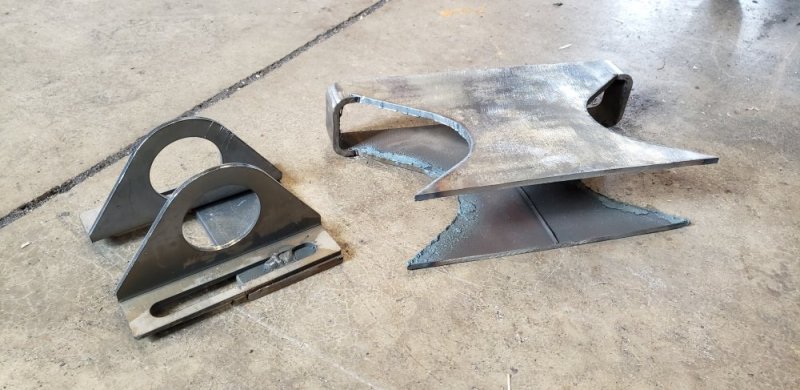
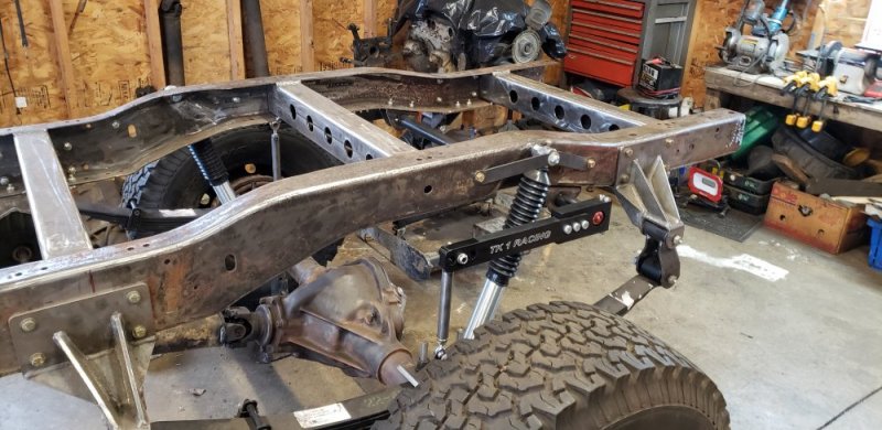
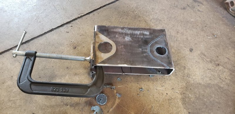
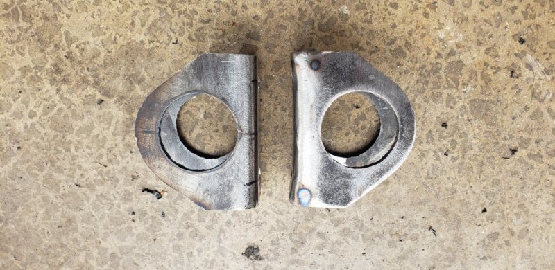
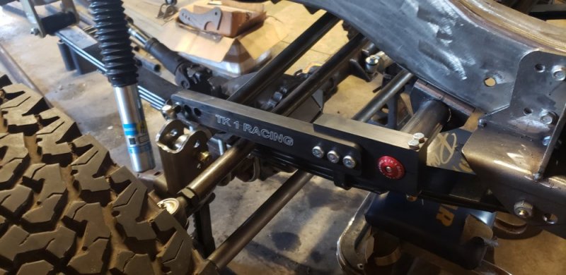
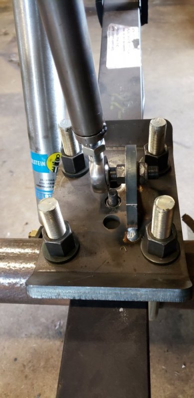
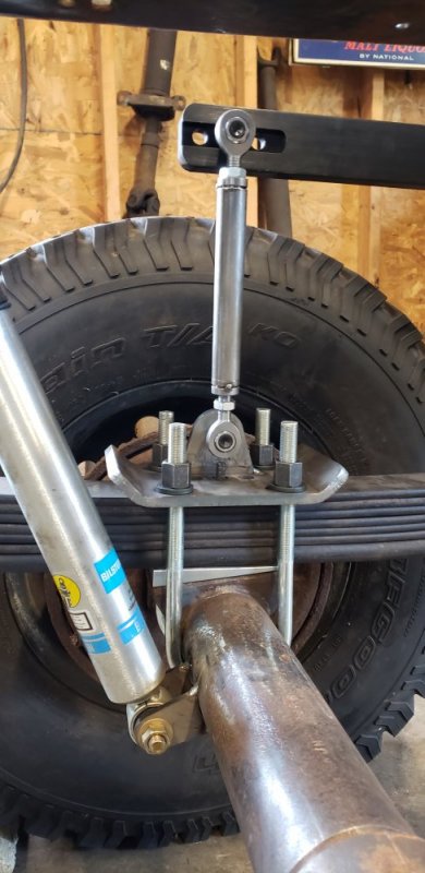
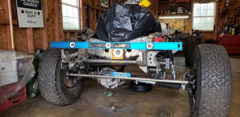
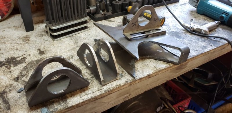
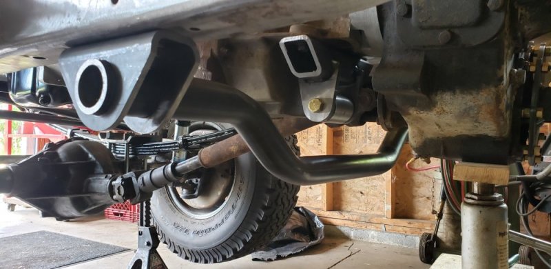
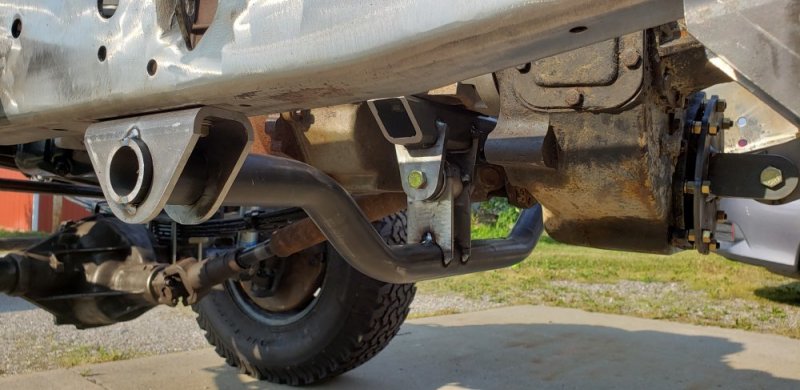
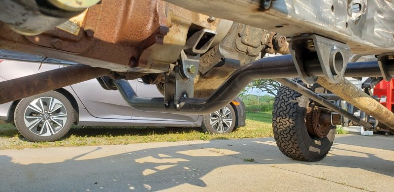
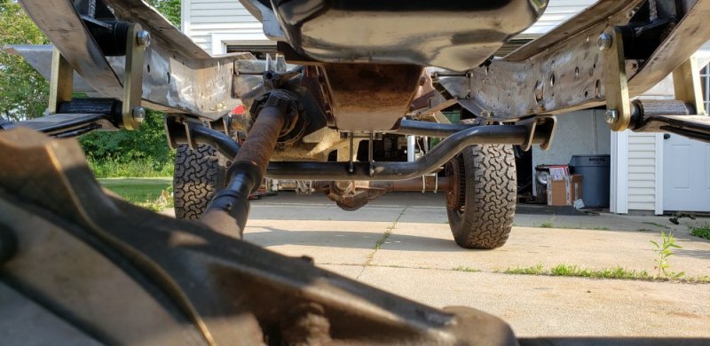
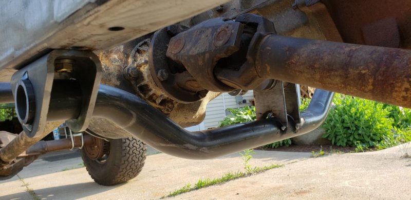
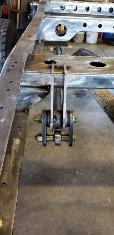
Well I drank entirely too much rum on Friday. So needless to say my Saturday was unproductive. But I had some time today to get back to work. Decided to switch gears since I'm waiting on the axle shims so I started working on the sway bars. The rear seemed like a good place to start. I'm using a 1" torsion style sway bar from Tk1. But I'll be making my own frame mounting brackets because the ones in the kit felt "cheap" to me. They are made from .125" with a 90* bend. I decided to step up to a .180" piece of box steel to make my mounts from. Box steel is awesome if you want a nice looking piece and don't have a press brake. I've been using it alot on this project. I liked the look of the provided mounts so I turned them into a template. I purposely used a larger piece of steel than I needed to avoid using the weld seem in any of my new frame mounts. With every thing squared up I cut the links to length and welded the tabs to the u bolt plates.
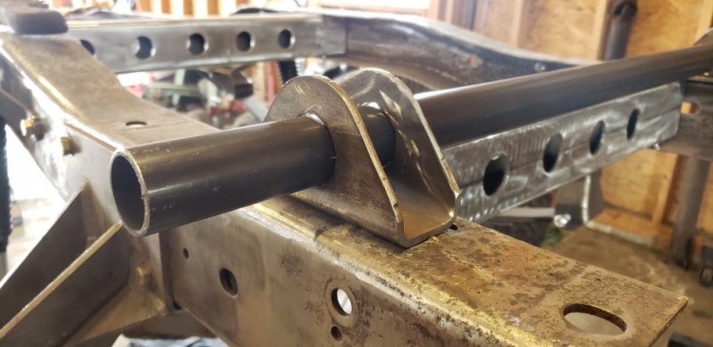
20200412_142509.jpg
20200412_142523.jpg
20200412_183244.jpg
20200412_183230.jpg
20200412_183255.jpg
20200412_183045.jpg

I'm going to build similar mounts for the front and get it installed next week. Then back to the crossmembers. I'm running out of time with the weather getting nice though. Thankfully I only have a few projects on the house to get done so figures crossed I wont take a 6 month hiatus from Johnny....
 
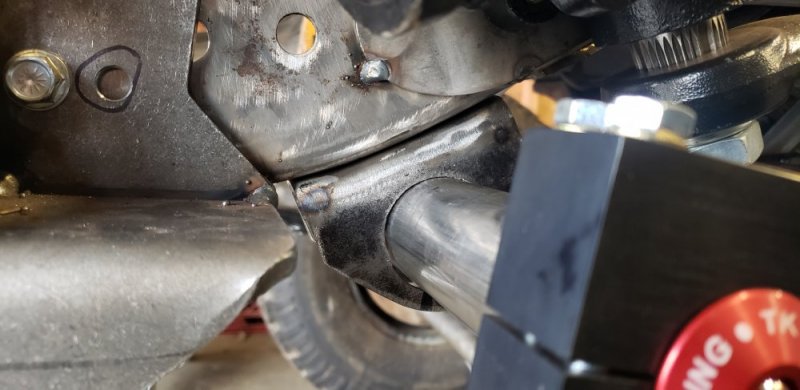
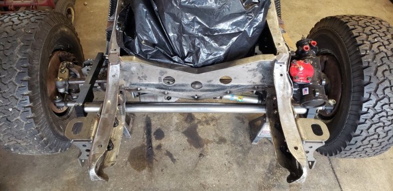
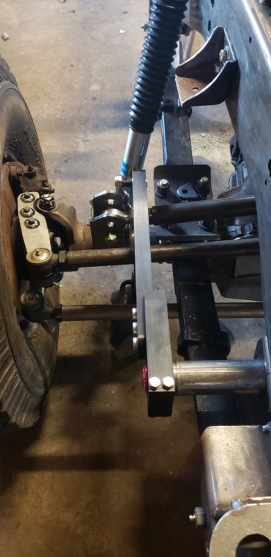
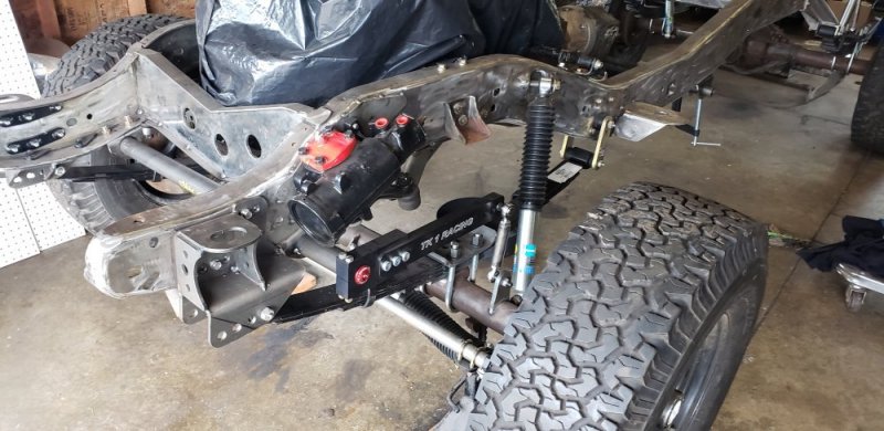
What I thought was going to be a nice easy day of putting my front sway bar in turned out to be quite stressful. I mean after you figure out the first one the second one is always easier.... so they say lol. The issue with the front is there is a huge difference in the frame rails do to the steering box mounting area. And wouldn't you know it that's right where my bar has to go. I started by cutting frame mount brackets similar to the back with my free jig. I don't have as much room up front so I made them shorter in height and length.
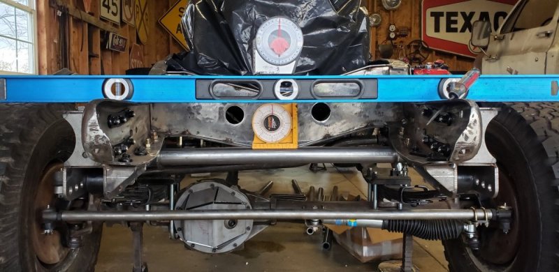
Now I have two issues to deal with. First the mounting area on the drivers frame rail has a curve so I need to modify my bracket to match. Secondly the location of the holes for the bar will not be centered in either bracket if I want to level it to the frame and tie rod. The first one was easy, a few slices with the grinder and I bent the mounting face to match the frame. Welded the gap and smoothed it out. The location of the holes for the bar on the other hand. Took probably two hours of mock up and measuring to get it right. But it was worth it!! I still have to work with it a little but so far it coming together.

20200419_113546.jpg
20200419_150041.jpg
20200419_181324.jpg
20200419_181332.jpg
20200419_181428.jpg

I have to finish the links and tack it all together. But I've decided to upgrade the single shear tabs from 1/8" to 3/8". I order some tabs for the rear too. Just like the "cheap" frame brackets provided with the kit these don't seem heavy duty enough.

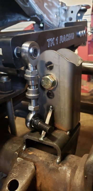
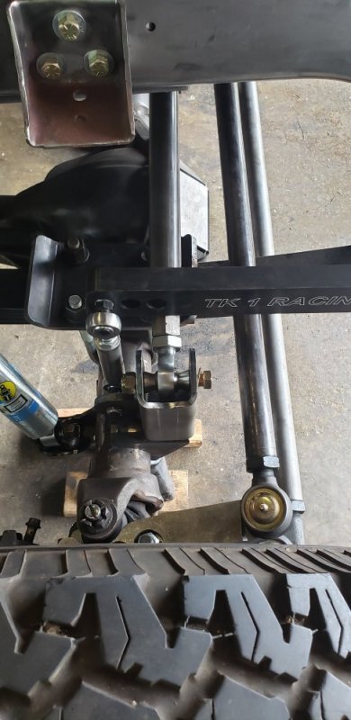
There is alot going on on the passenger side of the axle. Its coming together better than I had hoped. The sway bar lines up with the support gusset on the track bar bracket PERFECTLY! So I'm going to change it out for a piece of 3/8 with a mounting hole for the sway bar link. This makes all the work and headaches worth it! Maybe I can FINALLY finish the front suspension this week!!
20200420_182718.jpg
20200420_183008.jpg
20200420_183000.jpg
 
Its been hard to find the time and motivation to get back into the garage. We haven't slowed down at work much at all with the pandemic going on. I've been bombarded by our fleet customers getting ready for summer. But I'm very thankful for that!! On top of that, the last few weeks have kept me busy with my off time. We ended up buying a new car with our stimulus checks. I really wanted a TIG welder but my s10 is SOOOO rusted I'm sure its illegal to drive In a few states. My GF realized how much money she was spending on gas driving the Tahoe since she was stuck at home for 6 weeks. So we ended up getting a 17 civic and I'm taking over driving the Tahoe. That was probably the smarter way to use that money anyway. Then with the weather getting nice I had to get out and get the yard cleaned up. But to do that I finally had to fix my lawnmower. It's a older Ferris and I've been fighting electrical issues for years. So I ended up rewiring the whole engine, and doing my yearly maintenance on it.

Also starting this week I've had to pick up alot of responsibilities around the house. With Ohio getting the clear for elective surgeries my GF was finally able to get her carpal tunnel surgery. She is a cake decorator and after years of squeezing icing bags she has developed ALOT of pain in her hand. On top of being beautiful she takes care of me and the house. So it's my turn to return the favor while she recovers. But that's enough about my life back to the truck.

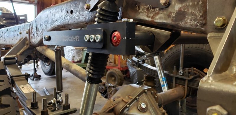
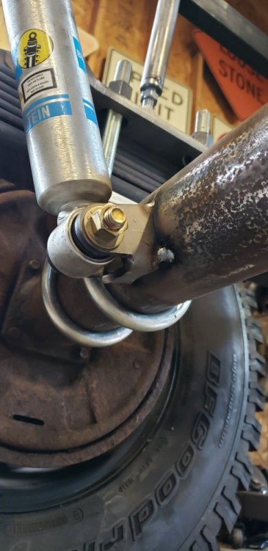
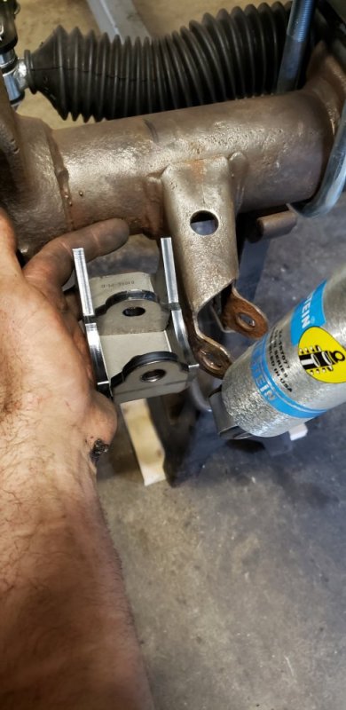
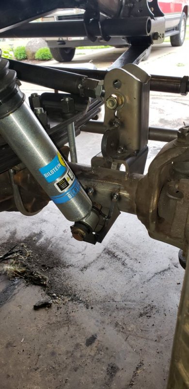
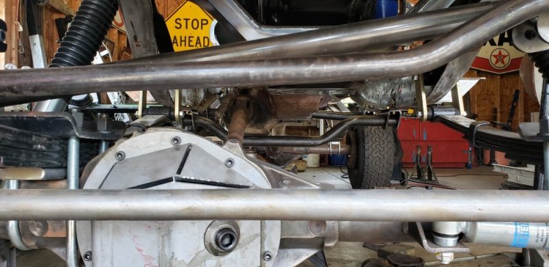
I did get into the garage to get some stuff done. I pulled the rear end to install the angled pinion shims. I remember the shock mounts being in rough shape. When I got it back apart I decided it was a good time to just replace them. Everything else is new so I might as well make the shock mounts look good too. I picked up some aftermarket brackets from ruff stuff. To install them I had to swap out the lower bushings since the new mounts are 1.5" wide and the Chevy uses a 1.625" wide mount. I picked up some new bushings and sleeves from Bilstein. The only issue is the 5100 shocks for the k20 use a different eyelet than the standard 5100 series shocks. The bushing will work for mock up, but I'm going to have to find a better solution down the road. Then I turned my attention to the sway bar link mounting brackets. I removed the flimsy 1/8" tabs from the u bolt plates. Then installed the new 3/8" tabs in a slightly different location. These not only look better but I'm sure they take alot more abuse. Being a single shear mount I was worried about how the 1/8" tabs would hold up. No need to worry about that any more. That almost finished up the rear suspension. The traction bar will have to wait till I get the drive line angles set and the transmission crossmember built.

20200509_180700.jpg
20200509_180636.jpg
20200509_180605.jpg
 
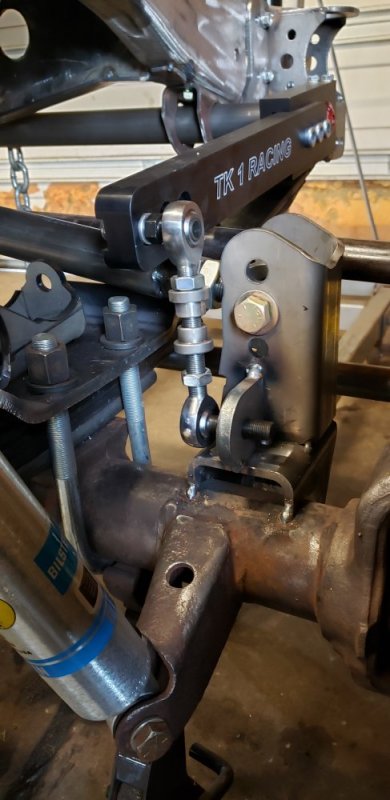
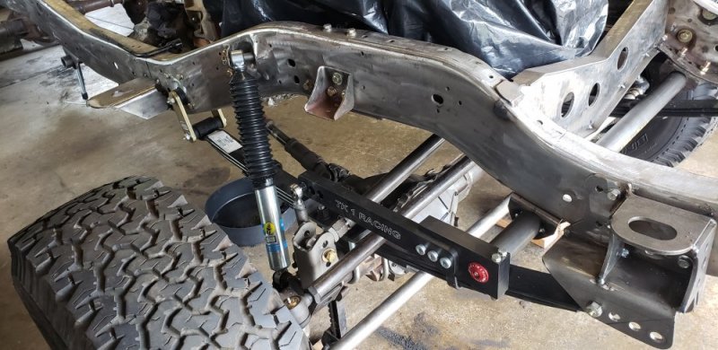
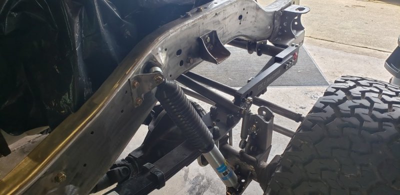
Then I moved onto the front end. I removed the gusset on the track bar bracket I built to install a mounting tab for the front sway bar link. Again its made from 3/8" and with a little cutting it fit in there perfectly. I was going to get the other side done but it comes in contact with the stock front shock mount. So I'm going to pull the front axle so I can cut the front shock mounts off and make room for the new shock brackets and driver sway bar mounting bracket. Again I got some shock mounting tabs from ruff stuff. They are unwelded so I can fit them how I like. Now I know it's a good idea to keep the mounting locations for the shock parallel. But I've seem plenty of off road rigs with non parallel mounted shocks. So I'm going to see if these brackets will work. As long as it doesn't bind it should be good to go. Once I get the old brackets out of the way I will have a better idea if it will work.

20200509_180739.jpg
20200509_180845.jpg
Once all that is done I can build the front links and the front end will finally be done!!

I started to lay out the transfer case crossmember just for fun. Should be really easy and straightforward. At least I hope so anyway.20200509_180712.jpg
20200509_180727.jpg

I'm hoping to get back into the garage tomorrow. But if the weather is nice (calling for 80% chance of rain) I need to get some stone moved. A friend of mine let me borrow his front end loader. I always like to get stuff done quickly when I'm using someone else's equipment.
 
Progress has been a little slow on the truck the last two weeks. My GF is still recovering from surgery so I have been BUSY around the house taking care of everything. She has a gluten allergy so we hardly ever eat out or make boxed meals. So my cooking skills are improving nicely!! Also I got side tracked all last week with another project I have been researching for over a year. I'm very excited about this... more so come on that later.
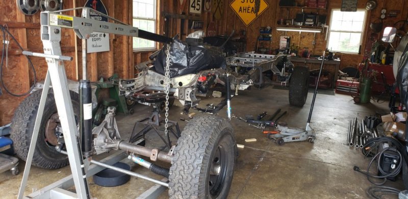
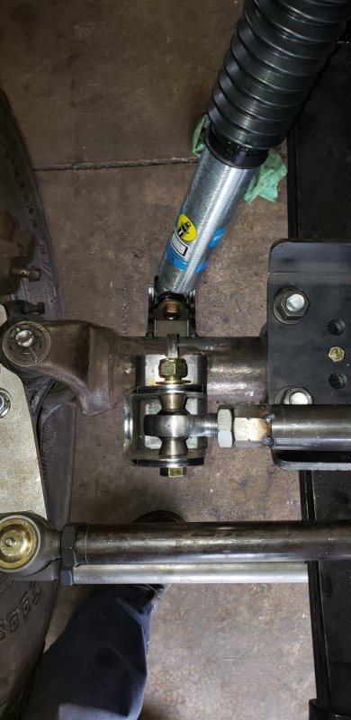
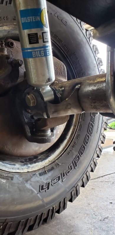
I removed the front axle last weekend to cut of the stock shock mounts. Wasn't to hard with the engine host and some careful planning. I could have left the axle in but it's much easier to grind sitting down vs on my back. I also had to trim the bottom side of the track back mount I made to clear the new shock mount on the passenger side. I was very careful not to cut into the axle. Then had to shorten the center brace to fit. Once everything was out of the way I reinstalled the axle to see If my new shock mounts would work. Surprisingly they almost worked with no modifications. I had to adjust the angle of the bolt hole tab just a little for it to line up with the shock eyelet angle correctly. That means the inner mounting bolt plate will need to be slightly longer. It's a good thing these came unwelded so I can make all the modifications I needed to make them fit. I'm going to email ruff stuff to see if they will cut me a longer inner mounting plate. I could probably make them but im sure they can cut them for cheap and they will match perfectly. Before I welded the mounts on I checked for any binding in the shock since I turned the eyelet about 60* to be parallel with the axle. I found zero issues and it had plenty of movement in all directions. If I was running a huge flexing coil spring suspension with tons of travel they may not be ideal. But with my leaf springs I dont see me having any issues. So I tacked them in and called it a day
20200517_133815.jpg
20200517_180959.jpg
20200517_181031.jpg
20200517_181055.jpg

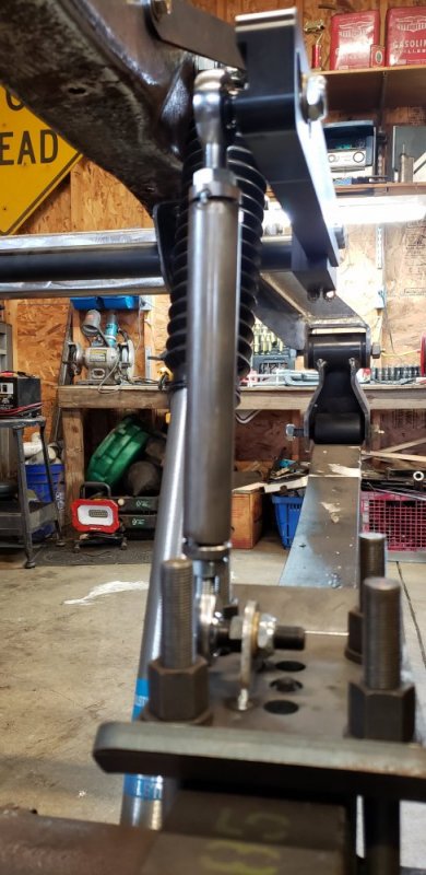
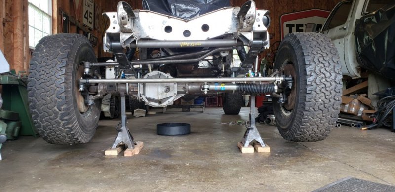
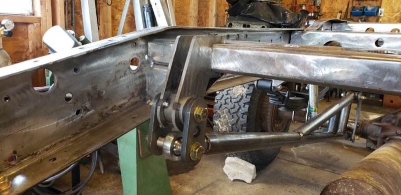
Next I moved onto the sway bar. I finally got the bench top belt/disk sander I inherited from my GF's father up and running. Man I should have done that months ago!! Boy did it do a nice job cleaning and squaring up the mounting brackets I made. I should have taken a before and after picture but I never remember to take pictures as I'm working. After what felt like forever I got the sway bar level and square to the frame. Then it was time to build the links and tack it all together. For the drivers side I went with another 3/8" tab over those flimsy 1/8" ones provided in the kit. I shortened it a 1/4" to match the height of the drivers side. And with that the front suspension is done... other than hours of finish welding😂.
20200517_192300.jpg
20200524_153948.jpg
20200524_153957.jpg
20200524_154017.jpg
20200524_154011.jpg
20200524_154030.jpg
 
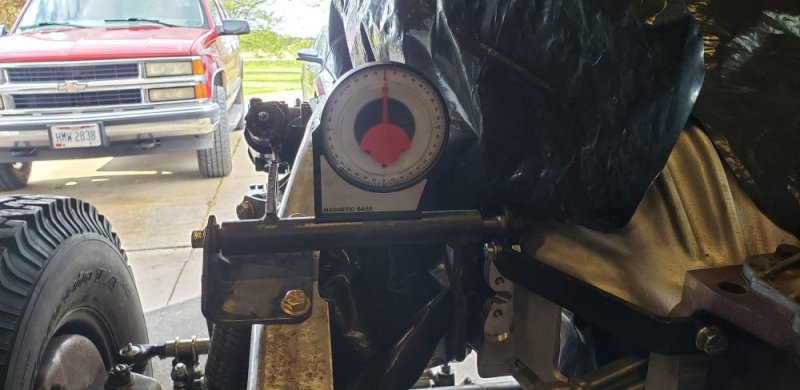
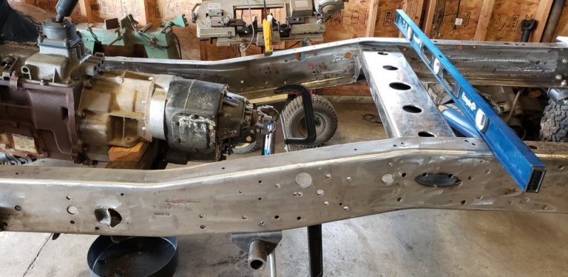
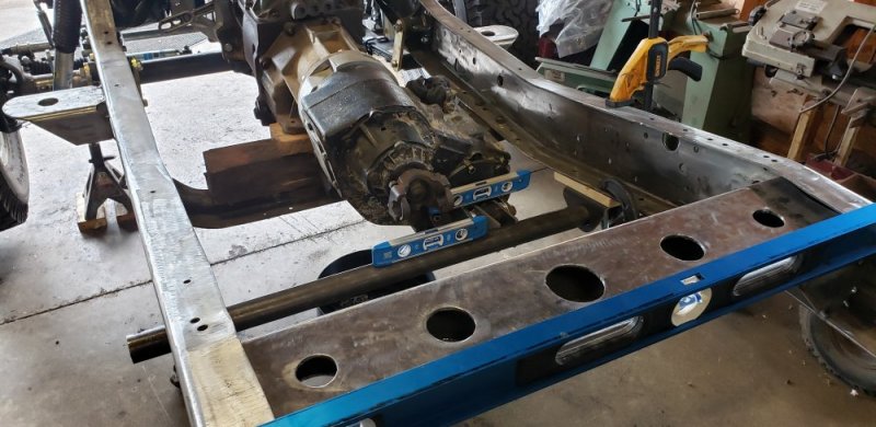
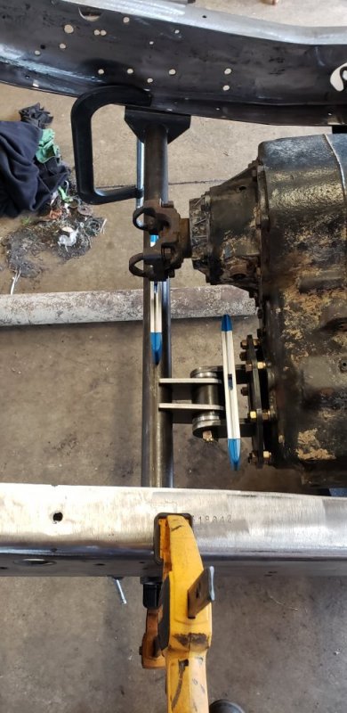
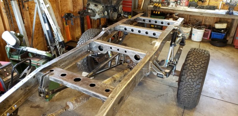
With the suspension wrapped up it was time to move onto the transmission and transfer case crossmembers. But to do that I had to level the frame at all 4 corners and set the drive line angle. I decided to install the z bar to see how it lined up with everything. I didn't want to adjust the drive line angle and end up with the z bar way out of whack. I ended up dropping the transfer case down a little to give it the 5* angle that I wanted. To my surprise the z bar ended up perfectly level!! So with the transfer case yoke at 5* and my rear end at 7* a CV joint in my rear drive shaft will be at the perfect 2* offset. So I should have ZERO drive line vibration.
20200525_183014.jpg

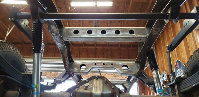
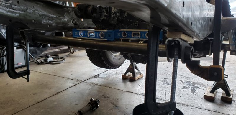
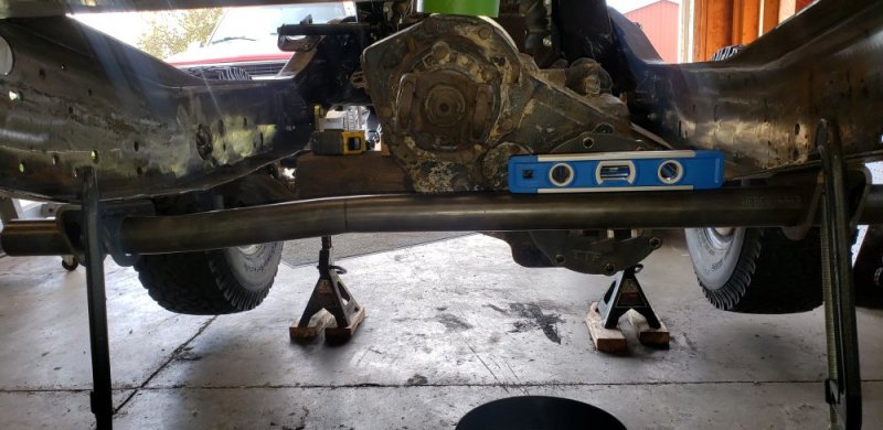
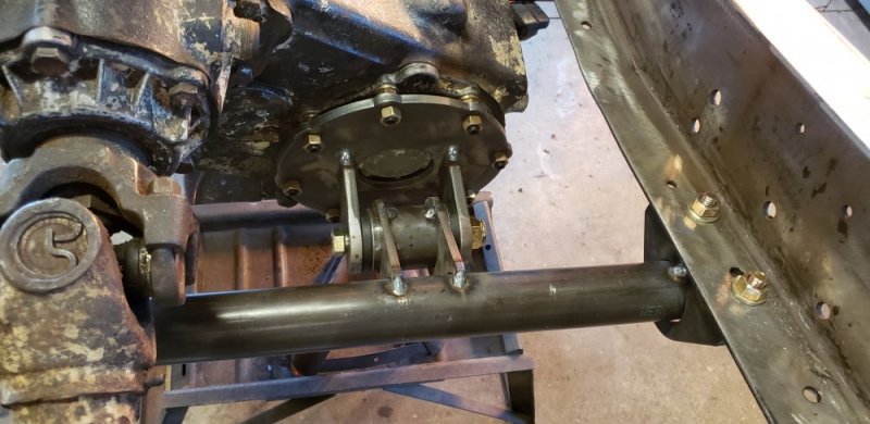
I then moved onto cutting my mounting brackets for the tube steel I'm going to use for the transfer case crossmember. These will be identical to the ones I made for the sway bar but out of .250" wall square steel to give it more strength. Everything that connects to the drive train is .250" so far. I cleaned them up on the disk sander (how did I go this long with out one!!) And started to mock everything up. Well I ran into a slight issue with a easy solution. There is a difference between the height on the frame rails from side to side. The bend on the drivers side is taller so when I clamped the bar and brackets into place it was 5* off level. I was able to level it out by installing a 3/4" thick piece of wood under the passenger mounting bracket. The easy solution to that is to put a z bend in the tube so can level it out. I could build a taller bracket for the passenger side, but I don't think I will like how that will look. The only issue is I dont have anything here to bend tube let alone .250" wall tubing. So I'm going to take the tube to a friend of my boss that builds roll cages for drag cars and see if he can put a bend in it for me. Once I get that done the transfer case crossmember should be ready to tack together.
20200525_184844.jpg
20200525_184430.jpg
20200525_184506.jpg
20200525_184457.jpg
 
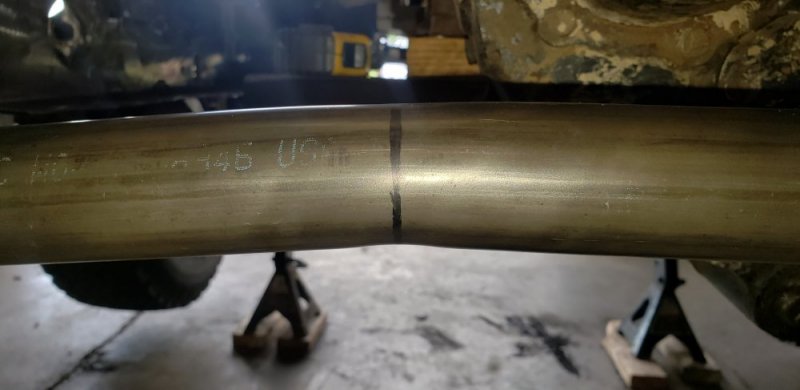
So after thinking it over... I decided that the .250" wall DOM might be a "little" overkill for the transmission and transfer case crossmembers. So I picked up some .180" wall DOM in the same 1.75" OD.

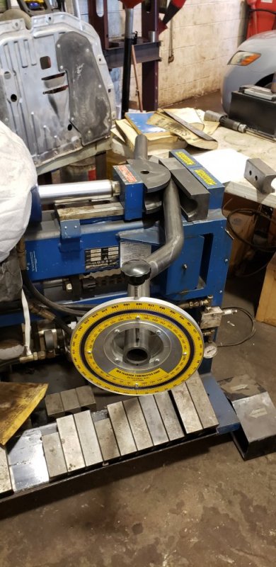
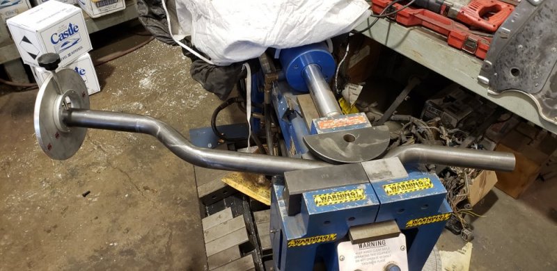
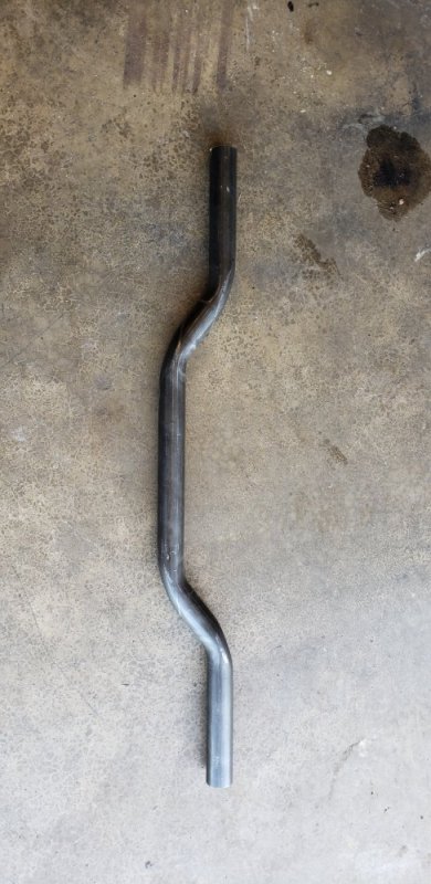
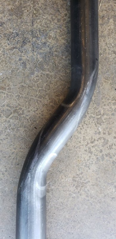
I actually was able to bend this at work on our Bendpak ram style exhaust bender... Yep I bent DOM on an exhaust bender and it came out great!! After doing the math I figured out where I needed to make my two bends. First calculated it up for two 10* bends at around 4.5" apart. But the flat dies are 6" long so I dropped it to two 5* bends to increase the center of bend distance to 8". I could have used the short die for the 10*, but I wanted as much support on the pipe as possible because I've never tried to bend DOM on this bender before. A 5* bend is nothing so I figured I would give it ago. I zeroed the pipe with my degree wheel, set it to 5* and let it rip. After the first bend I removed the pipe and measured what I actually got degree wise since I was anticipating some spring back. It measured 3*, so I put it back in and took it to 7*. That gave me the 5* I was after. Next I moved it 8", rotated it 180* and did another 7* bend. This is some simple bending, but I'm pleased with how it did. Got the 3/4" offset I was after. And it's perfectly level in the frame now. Still need to square it up and weld it but at least the pipe is bent.
20200601_183449.jpg
20200601_183510.jpg

The transmission crossmember is going to be more of a challenge. I'm not sure how far I can go with the ram bender before is distorts the tube. Once I measure it out I will see if I think its doable.
 
Its been hard to find the time and motivation to get back into the garage. We haven't slowed down at work much at all with the pandemic going on. I've been bombarded by our fleet customers getting ready for summer. But I'm very thankful for that!! On top of that, the last few weeks have kept me busy with my off time. We ended up buying a new car with our stimulus checks. I really wanted a TIG welder but my s10 is SOOOO rusted I'm sure its illegal to drive In a few states. My GF realized how much money she was spending on gas driving the Tahoe since she was stuck at home for 6 weeks. So we ended up getting a 17 civic and I'm taking over driving the Tahoe. That was probably the smarter way to use that money anyway. Then with the weather getting nice I had to get out and get the yard cleaned up. But to do that I finally had to fix my lawnmower. It's a older Ferris and I've been fighting electrical issues for years. So I ended up rewiring the whole engine, and doing my yearly maintenance on it.

Also starting this week I've had to pick up alot of responsibilities around the house. With Ohio getting the clear for elective surgeries my GF was finally able to get her carpal tunnel surgery. She is a cake decorator and after years of squeezing icing bags she has developed ALOT of pain in her hand. On top of being beautiful she takes care of me and the house. So it's my turn to return the favor while she recovers. But that's enough about my life back to the truck.

I did get into the garage to get some stuff done. I pulled the rear end to install the angled pinion shims. I remember the shock mounts being in rough shape. When I got it back apart I decided it was a good time to just replace them. Everything else is new so I might as well make the shock mounts look good too. I picked up some aftermarket brackets from ruff stuff. To install them I had to swap out the lower bushings since the new mounts are 1.5" wide and the Chevy uses a 1.625" wide mount. I picked up some new bushings and sleeves from Bilstein. The only issue is the 5100 shocks for the k20 use a different eyelet than the standard 5100 series shocks. The bushing will work for mock up, but I'm going to have to find a better solution down the road. Then I turned my attention to the sway bar link mounting brackets. I removed the flimsy 1/8" tabs from the u bolt plates. Then installed the new 3/8" tabs in a slightly different location. These not only look better but I'm sure they take alot more abuse. Being a single shear mount I was worried about how the 1/8" tabs would hold up. No need to worry about that any more. That almost finished up the rear suspension. The traction bar will have to wait till I get the drive line angles set and the transmission crossmember built.

View attachment 60613
View attachment 60614
View attachment 60615
Are you going with quick release link fasteners for off road, or? "That is an awesome build."
 
You can cap the end and fill it with sand if it distorts.
That thinner dom is still crazy stronger than any factory cross member.

I had thought about filling it with sand if I need to do some higher degree bends. Once I measure everything out I can make a better judgment on that.

Are you going with quick release link fasteners for off road, or? "That is an awesome build."

I'm not sure yet. I was originally planning to do some off roading with this rig. The more progress I make on it, the more I feel it wont not see alot of "Hardcore" trails. I might make a set of quick disconnect links that I can put on for light trial use. I'm not worried about the chassis, but the body takes a beating in the woods and after it's done I'm going to have a hard time beating it up lol.

Thanks, I've been waiting ALONG time to put this truck together. Opening the wallet all the way💸💸💸
 
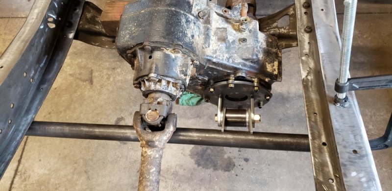
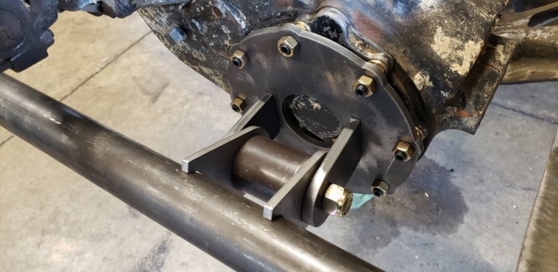
Last weekend I finished up the transfer case crossmember. Not much to add on to what I've already showed you guys. I cut the pipe to length, leveled and squared up all the brackets. Then tacked it all together. With that now holding the drive train from moving. I removed the transmission crossmember and started to mock up the transmission crossmember tubing.... more on that later.

20200607_203059.jpg
20200607_203114.jpg

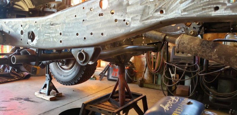
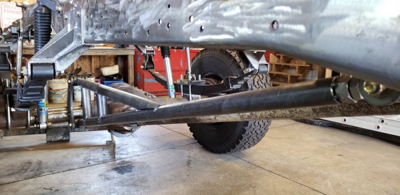
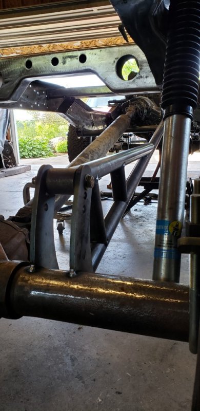
This weekend I decided to tackle the traction bar. I tried to start on it last weekend, but realized my new tubing notcher requires a drill with a 1/2" chuck. I dont have one here at the house, so I made sure to bring mine home from work this weekend. I got the traction bar kit from Ruff Stuff. It's a universal kit that comes with a few pieces of .250" wall tube, brackets, bushings and a heim joint. Originally it had a 2" lower tube and a 1.75" upper tube. But after looking at it the lower tube just seemed MASSIVE. So I got another piece of 1.75" × .250" for the bottom tube.

This seemed like a straight forward install.... but it took me most of the weekend to dial it in. Suspension parts require ALOT of measuring and adjusting to get it right. This was the first time I've installed this kinda of traction bar so I took my time to get it right.

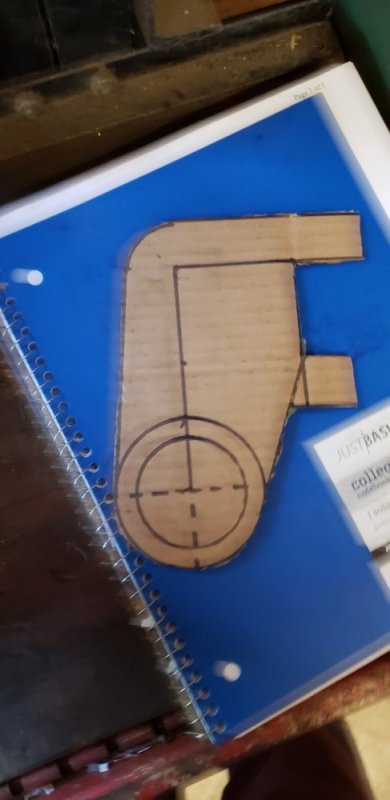
First I notched the upper and lower tubes so I could tack on the bushing boss for each tube. Then I cut the lower tube to the same length as the drive shaft when measuring from the center of the bushing to the center of the heim joint. Next I pressed in the rear bushings and installed both tubes into the axle brackets. That kept everything square so I could line up the brackets on the axle. Ruff stuff said I could install the axle brackets at any angle I wanted. But I decided to set the center line from the upper to lower mounting bolts perpendicular to the floor. That made the most sense to me. With the axle bracket clamped in place I set the lower tube to the same angle as the drive shaft. Then I assembled the front shackle with the bushing and boss to square it all up when I tightened the bolts. Last I set the shackle to 90* off the lower bar. With all that lined up I could finally measure for my front mounting brackets. The kit came with brackets to mount to a tube crossmember. But since it lined up really close with my existing crossmember I thought I would build custom brackets to mount it off of that. I measured out the location of the bracket and made a cardboard template.

20200613_161950.jpg
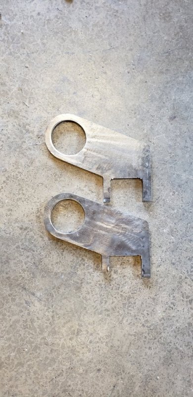
This is what I started with and bellow is what I ended up with. I trimmed a little more off of it because after I cut them out they felt "Bulky" to me. The brackets are made from 1/4".

20200614_132435.jpg

With those cut out I installed them over the bushing boss and lined them up on the crossmember. This was time consuming as hell to get everything to lined up and hold it square. But after a using what felt like every 90* magnet and clamp I had I managed to line it up and tacked it in place.

Next I notched the upper tube to attach it to the lower tube. With the frame being level still I set the upper bar to be level with the frame. Lastly I notched a few tubes to go between the upper and lower tubes. I got 2 out of 3 finished before I had to stop for dinner. The last one is too short to fit in my notcher so I will have to do the last notch by hand. Shouldn't take me long to finish that last tube some day this week.

20200614_173444.jpg
20200614_173425.jpg
20200614_173501.jpg
20200614_173529.jpg
20200614_173556.jpg

The upper tube looks short because the lower is almost 5ft long. I could have made the upper longer put then it wouldn't have been level to the frame.
 
Last edited:
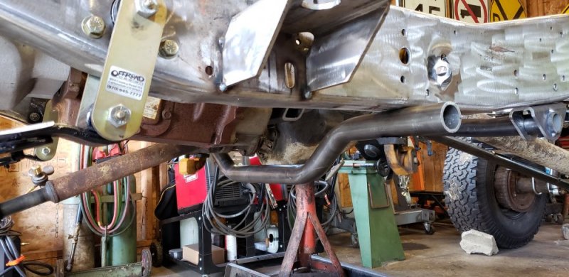
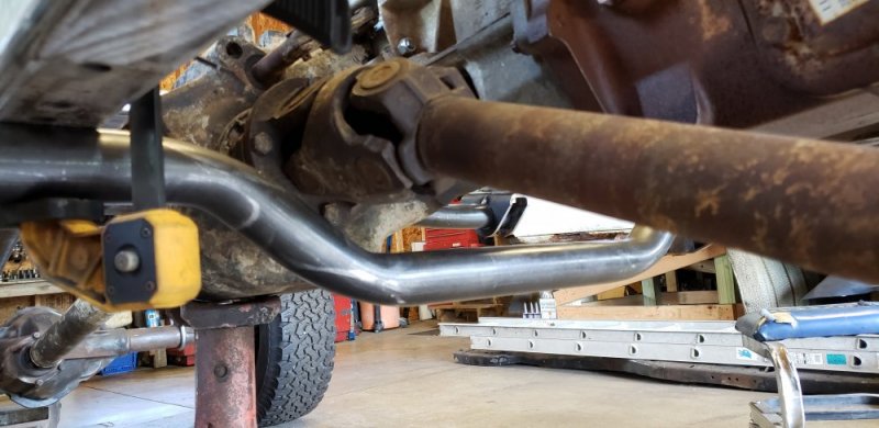
Back to the transmission crossmember... I leveled the pipe under the frame and measured out what I needed to do as far as bends. I calculated up two, 2" offset bends at 25*. So I decided I was going to take a chance and try the exhaust bender again and see what it could do... Well I quickly found out it was more of a challenge than I expected. The short shoe had a hard time keeping square when I was doing the second bend in the offset. But after some back and forth between the different shoes on each bend I got something I was happy with. The only thing is after I finished I ended up with a 3" offset at 35*. I was worried it wasn't going to fit because I calculated shrinkage for a 25* bend. To my surprise it fits AWESOME! I think the extra inch of drop works out well because it sits just below the transfer case to add some protection. And the increased angle in the bends helped me get more clearance at the front drive shaft. So it ended up being a good mistake.

The bends didn't turn out to bad either. The inside of the bend looks perfect. The outside flattened a little, which I expected when using this style bender. A mandrel is really the only way to prevent that and I don't have access to one of those. Next weekend I'm going to build the mounting brackets and bushing boss brackets. That should finish the chassis work and I can finally move onto body work.

20200612_172057.jpg
20200612_172105.jpg
20200613_151802.jpg
20200613_151813.jpg
20200614_173823.jpg

20200614_173836.jpg
 
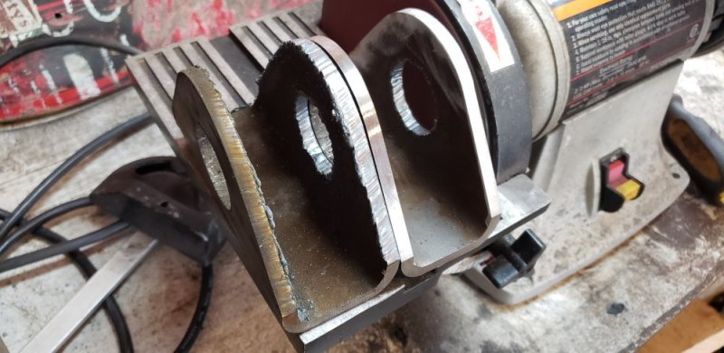
Well after a busy week of side work I some how fell into, I got some time to finish the transmission crossmember. I made a set of mounting brackets the same way I made the rest. This time I actually took some pictures of them. Again this is from 2"×6"×.250" welded seam box steel. I use my template to rough cut them, then finish them up on the disk sander. I avoid using the welded seam in any of the brackets I build so I order a slightly larger piece than I need.
20200621_122107.jpg
20200621_131119.jpg

I ended up moving the crossmember over to the passenger side. It gave me more drive shaft clearance. And I thought it looked better offset. The new brackets used the original transmission bolt locations. With those bolted in place I was able trim the crossmember to length.
20200621_155957.jpg

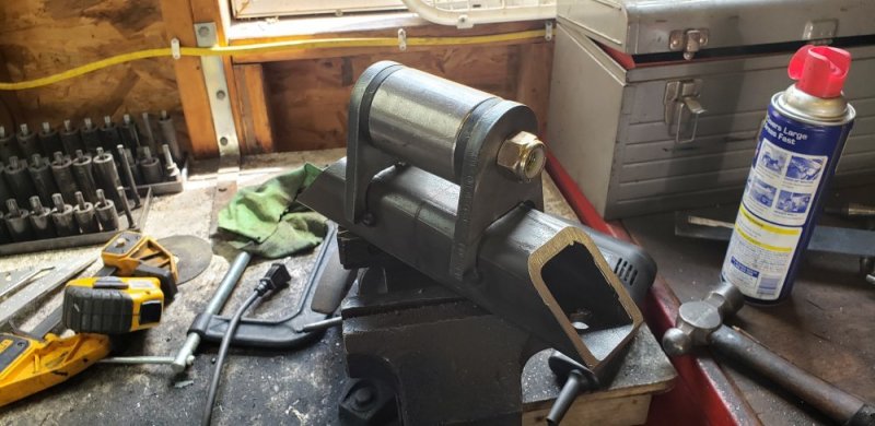
Next it was time to build the transmission mount. I made this from 2"×2"x.250" square steel that I angle cut on the band saw. Then notched two 3/8" tabs to fit over it for the bushing to mount to.
20200621_145948.jpg

20200621_155943.jpg

With that bolted in place I built the last two brackets. These are similar to the ones I used on the transfer case mount. Made from 2"x.250" steel I cut the one end to wrap around the bushing boss. And the other to mount to the crossmember. Super simple but still look nice
20200621_182900.jpg
20200621_182918.jpg
20200621_182928.jpg
20200621_182939.jpg
 
Back
Top