• Welcome to The Truck Stop! We see you haven't REGISTERED yet.

    Your truck knowledge is missing!
    • Registration is FREE , all we need is your birthday and email. (We don't share ANY data with ANYONE)
    • We have tons of knowledge here for your diesel truck!
    • Post your own topics and reply to existing threads to help others out!
    • NO ADS! The site is fully functional and ad free!
    CLICK HERE TO REGISTER!

    Problems registering? Click here to contact us!

    Already registered, but need a PASSWORD RESET? CLICK HERE TO RESET YOUR PASSWORD!

4wd Actuator

Starting at 15:05 in this video, I could not perform the tests he did for the A and B circuits, or I could not get power across them.


I get 12.54v at the yellow arrows when grounded to the frame. In his video he's commanding A and B circuits at the red arrows and getting a test light to work when connected there. I can't replicate that, but he was using his diagnostic tool to make the commands. I would have to explain to my wife how to do that, then have her do it while I'm under the truck. I need to fab up some test lights with probes like his.
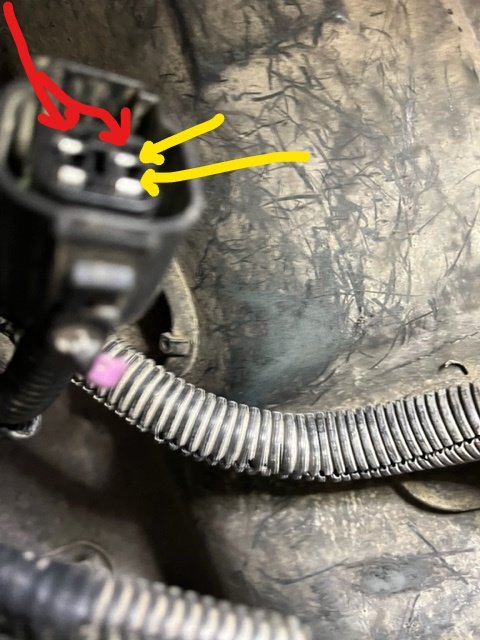
Encoder Harness.jpg
 
Last edited:
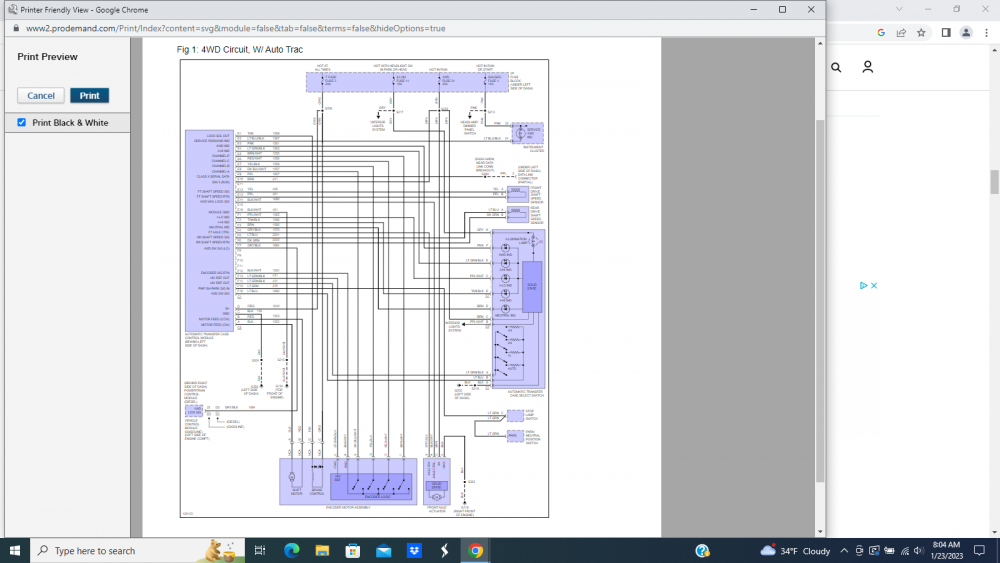
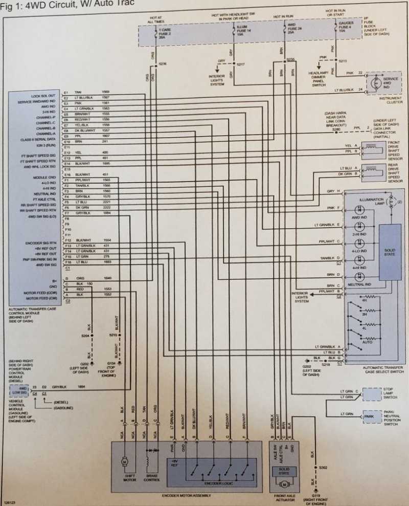
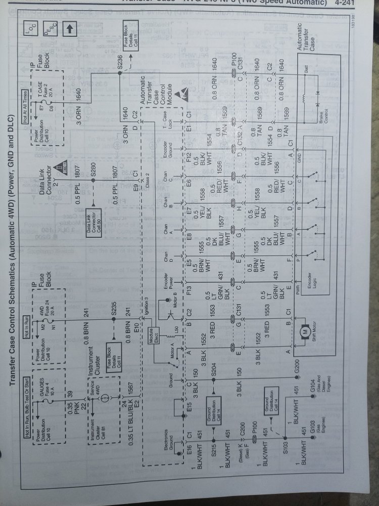
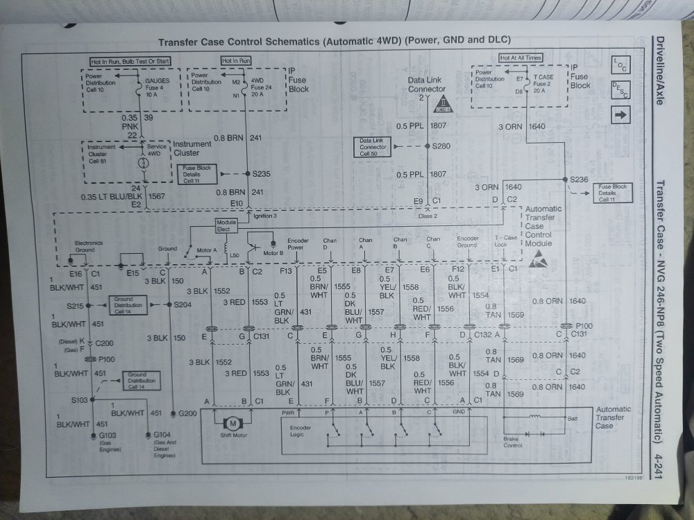
Sorry I haven't been on here much lately. Too much side work keeping me busy. Here is the test procedures for no 4WD low and a screen shot of the wiring diagram. Hopefully you can read the diagram. ProDemand doesn't allow me to download the image so I have to screen shot it.

1. Select 4WD low, test voltage backprobed at the transfer case motor drive circuits, C1 terminal A to terminal B. Should be battery voltage for as long as the 4WD Low indicator is flashing.

2. Test voltage backprobed at the motor brake control circuit C1 terminal D. Should be battery voltage until 4WD Low is selected, then voltage should be 0 or near zero while the 4WD Low indicator is flashing.

3. Scan the encoder switches status. Test voltage backprobed at the encoder switches circuits. Compare to the information in tech tips. Compare when selecting 2WD, 4WD High and 4WD Low.

4. Repeat tests at Transfer Case Shift Control Module connectors.

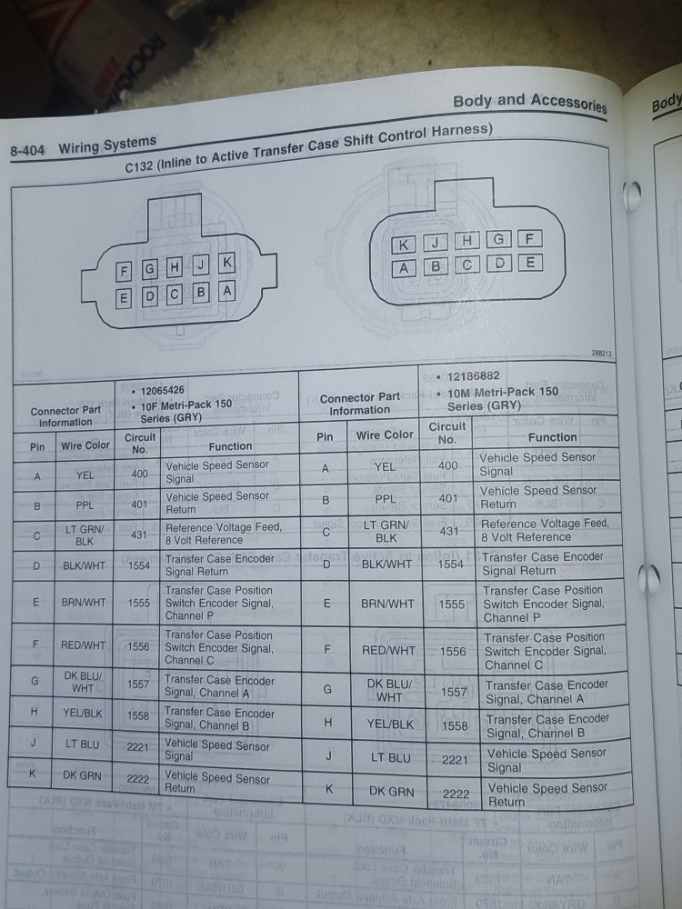
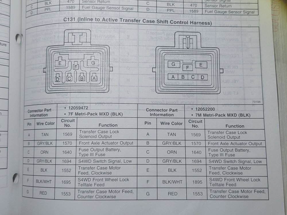
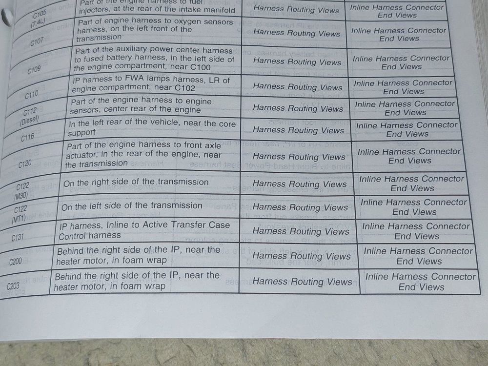
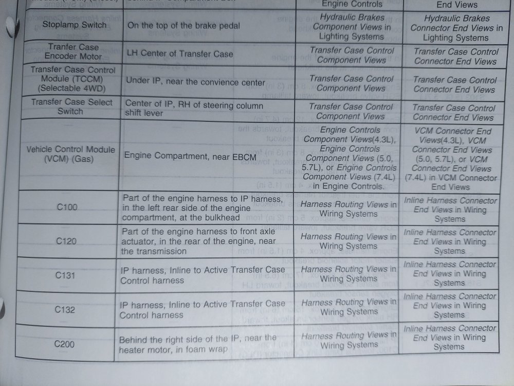
5. Inspect C131 and C132 connectors, terminals, wiring for damage, corrosion.

6. Test wiring from Transfer Case Shift Control Module to in-line connectors, to transfer case encoder motor.
Tech Tips:Transfer Case Encoder Truth chart
CW = Clockwise, CCW = Counterclockwise
E5/P E8/A E7/B E6/C
5v/off 0v/on 0v/on 0v/on 4LO>35 degrees
5v/off 0v/on 5v/off 0v/on 4LO<35 degrees
0v/on 0v/on 5v/off 0v/on 4LO (AUTO) CCW
0v/on 0v/on 5v/off 5v/off 4LO (AUTO) CW
5v/off 0v/on 5v/off 5v/off Between Gears
5v/off 0v/on 0v/on 5v/off Between Gears
0v/on 0v/on 0v/on 5v/off Neutral
5v/off 5v/off 0v/on 5v/off Between Gears
0v/on 5v/off 0v/on 5v/off 2HI CCW
0v/on 5v/off 0v/on 0v/on 2HI CW
5v/off 5v/off 0v/on 0v/on 4HI (AUTO) Range <35 degrees
5v/off 5v/off 5v/off 0v/on 4HI (AUTO) Range>35 degrees
Screenshot (5).png
 
1. Select 4WD low, test voltage backprobed at the transfer case motor drive circuits, C1 terminal A to terminal B. Should be battery voltage for as long as the 4WD Low indicator is flashing.

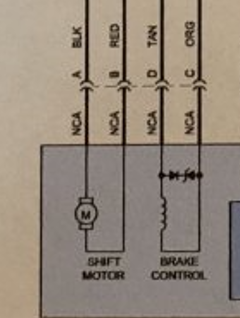
Separated the harness plug from the encoder harness and touched probes to A (black) and B (red) while my wife was depressing 4 Lo with ignition on and transmission in neutral. Voltage was 0.0.

1674496533070.png7.0

2. Test voltage backprobed at the motor brake control circuit C1 terminal D. Should be battery voltage until 4WD Low is selected, then voltage should be 0 or near zero while the 4WD Low indicator is flashing.

Tested Terminal D (tan) to ground showed voltage of 0.0 while in 2Hi and no change while pressing 4Lo.

Stopped my tests here.


3. Scan the encoder switches status. Test voltage backprobed at the encoder switches circuits. Compare to the information in tech tips. Compare when selecting 2WD, 4WD High and 4WD Low.

4. Repeat tests at Transfer Case Shift Control Module connectors.

Is this the module installed under the dash to the left (driver's side) of the steering column? If so, this is my next test.

5. Inspect C131 and C132 connectors, terminals, wiring for damage, corrosion.

It is not clear where these are located in the diagram.

6. Test wiring from Transfer Case Shift Control Module to in-line connectors, to transfer case encoder motor.

Did these tests at the 4 pin connector to the encoder motor harness.
 
The C131 and C132 are multipin chassis wiring harness connectors. They are located in the engine compartment. Give me a few minutes while I grab Vol. 1 of my 1998 GM C/K Truck Service Manual and find the Cell 38 (automatic transfer case) schematics and component location diagrams and I'll post them up here. Sounds like you have either a bad/corroded connector pin/socket in one of the chassis harness plugs or the battery (+) feed to that circuit is interrupted somewhere leading to the first connector or between connectors.
 
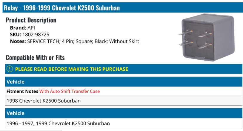
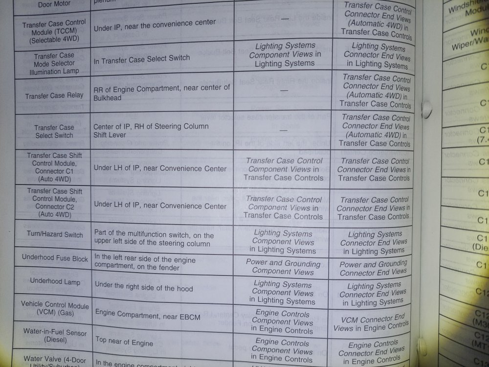
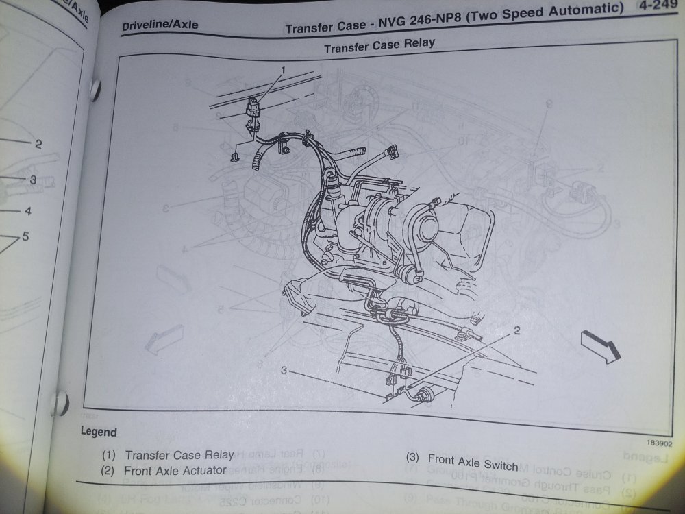
In checking my book, did you know that there is a Transfer Case Relay that provides power when energized by the Automatic 4WD Selector Switch when 4LO is engaged. It is located in the rear of the engine compartment near the center of the bulkhead (firewall)? Perhaps if that relay has gone bad is the reason why you have no power to the motor when 4LO is selected.
 
In checking my book, did you know that there is a Transfer Case Relay that provides power when energized by the Automatic 4WD Selector Switch when 4LO is engaged. It is located in the rear of the engine compartment near the center of the bulkhead (firewall)? Perhaps if that relay has gone bad is the reason why you have no power to the motor when 4LO is selected.
Learning as I go hear. Got a picture of it?
 
No "picture" of it that I can find in the Vol.1 Chassis and Accessories Wiring Section. It looks like I'll have to go to Vol. 2, Driveline/Axle Section, Transfer Case NVG 246-NP8, Page 4-237. You do realize that the printed version of the C/K Ttruck Service Manual is 4 Volumes that cover almost 9,000 pages (some sections are well over 800 pages, and the Sections are arranged out of order so that each Volume is approximately 2" thick). Let me go grab that Volume and see if there are any component location diagrams.
 
No "picture" of it that I can find in the Vol.1 Chassis and Accessories Wiring Section. It looks like I'll have to go to Vol. 2, Driveline/Axle Section, Transfer Case NVG 246-NP8, Page 4-237. You do realize that the printed version of the C/K Ttruck Service Manual is 4 Volumes that cover almost 9,000 pages (some sections are well over 800 pages, and the Sections are arranged out of order so that each Volume is approximately 2" thick). Let me go grab that Volume and see if there are any component location diagrams.
Sounds like the Toyota Manual for the 5th Gen 4Runner. I have a PDF copy saved, but its 8000 pages long and not searchable. When I was installing seat warmers, the discussion on seat disassembely started about page 7550 and I started at the front of the book to get there.
 
Ok, there is a TON of diagnostic, schematic and component location in Vol. 2! You REALLY should find a set of these on eBay or Amazon (or I also have the GM Service CD-ROM that lets you access GM's on-line data base, which is essentially a PDF-type copy of the physical manual, that I'd sell you cheap ($15+shipping) if you don't mind reading it on your laptop out in the drive/garage instead of "the books", if you want it.
 
Ok, there is a TON of diagnostic, schematic and component location in Vol. 2! You REALLY should find a set of these on eBay or Amazon (or I also have the GM Service CD-ROM that lets you access GM's on-line data base, which is essentially a PDF-type copy of the physical manual, that I'd sell you cheap ($15+shipping) if you don't mind reading it on your laptop out in the drive/garage instead of "the books", if you want it.
I will probably want the CD. Need to check my laptop in Fullerton if it has a CD reader. Or my son might have a laptop with a CD reader.
 
Back
Top