• Welcome to The Truck Stop! We see you haven't REGISTERED yet.

    Your truck knowledge is missing!
    • Registration is FREE , all we need is your birthday and email. (We don't share ANY data with ANYONE)
    • We have tons of knowledge here for your diesel truck!
    • Post your own topics and reply to existing threads to help others out!
    • NO ADS! The site is fully functional and ad free!
    CLICK HERE TO REGISTER!

    Problems registering? Click here to contact us!

    Already registered, but need a PASSWORD RESET? CLICK HERE TO RESET YOUR PASSWORD!

6.5TD motorhome starting problem

I removed the side terminal cables from my 2000 K3500. Took them over to NAPA and the parts counter person worked to put me together a set of top post terminal cables.
I believe it was about $175.00 for the complete positive cable system.
It sure makes a difference letting all those amps through the bigger wire. I’m always surprised somehow. Haha
 
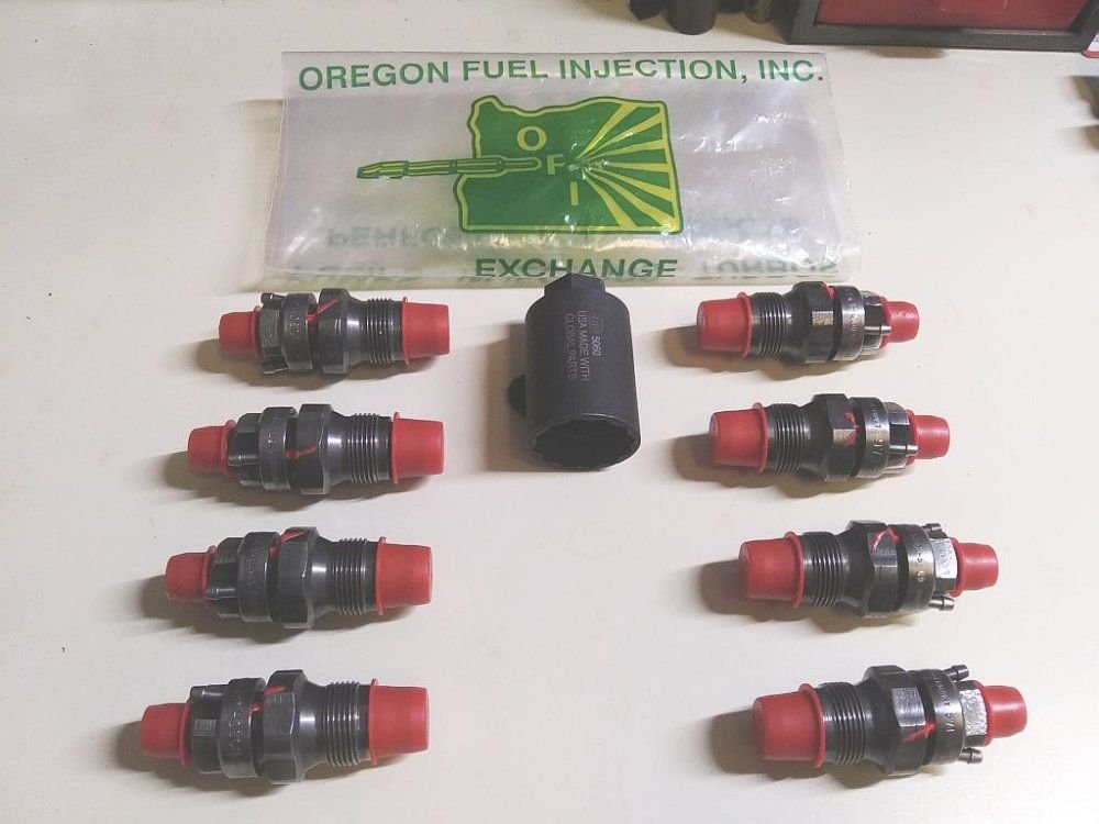
Will L. and everybody: I sent my old injectors to Oregon Fuel Injection, Inc. . (celebrating their 50th year in business). to have them rebuilt. See attached picture of the rebuilt injectors. The company stated the flow rate opening pressure is: 2175....with 2% spread max.

dbrannon79 and everybody: I have done the check you asked for starting at a fully charged new stand alone 12volt battery at 12.80 volts. I removed glow plug wire from glow plug relay (controller). Then removed all 8 glow plug wires. Checked voltage on each wire on driver's side....all read 12.79 volts. Check same on passenger side .... they read 12.41 volts.

Remember when I turn the key on using motorhome battery- at around 12.57 volts....the draw down is about 10.57 volts. and after glow plug light goes out...the starter motor turns over just fine.
Looks like glow plug wires going south on the passenger side- "going South"?
What do you all think?
 

Attachments

  • AAA. My rebuilt Injectors.jpg
    AAA. My rebuilt Injectors.jpg
    80 KB · Views: 4
2% @ 2175 is a good set up.
I don’t see pics of the glow wires you mentioned

Cranking rpm still needed
So is fuel pressure at the ip instead of ffm

If you are content with the start time by cycling the key 3 times - then run with it.
Otherwise there is things that could be done but will cost some $$
 
MrMarty51- Thanks for your come back.
Will L. : 4-8-25
Don't know what you mean about a picture of my glow plug wires?
I removed the glow plug wires from the glow plugs to check the voltage.

Cranking RPM: My Scan Gauge II will only give me the rpm after the engine starts.
Are you asking for the idle speed?

Your question: So is fuel pressure at the ip instead of ffm?
Still have to figure out what exactly you want here? Do you want me to add a fuel pressure gauge to the "T" fitting on the clear line?

I will do the 1/2 gallon lift pump test.
A Fuel Pressure test at the IP would be post FFM, right up next to the injection pump.
It would require installing a T in the supply hose right next to the injection pump then tapping a gauge into that T.
 
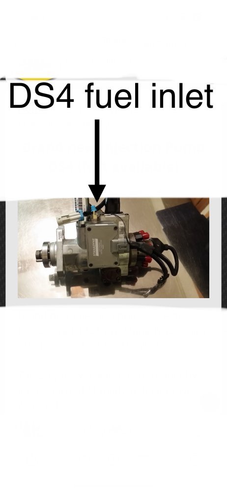
Marty explained it right. Measure the fuel pressure at the ip fuel inlet. See arrow in picture, with the blue cap on it.


IMG_3114.jpeg

As to the rpm- it needs to be while cranking before starting.
Sometimes people disconnect the wire to the fuel shutoff solenoid to stop the engine from starting to get an accurate reading.
 
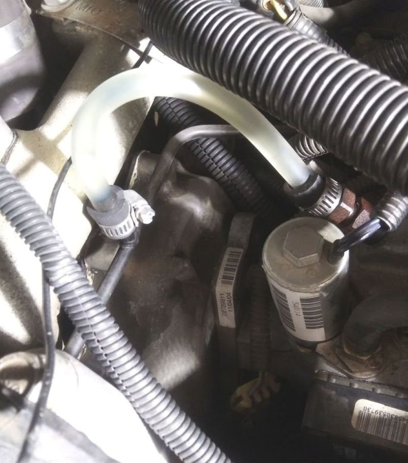
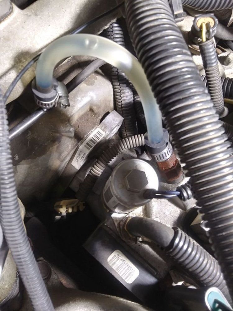
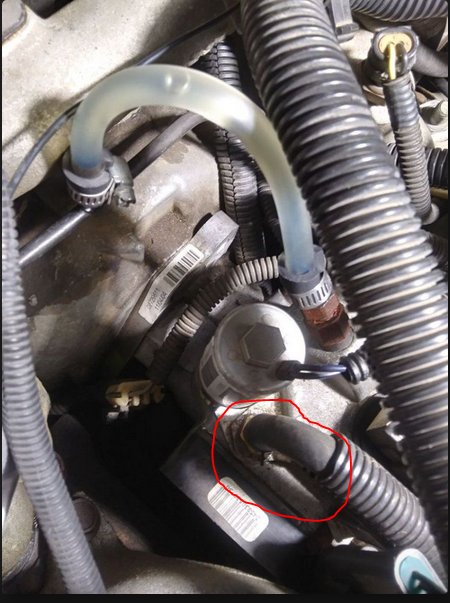
This is the picture of the clear hose that I put in a long time ago. Is this the place where you want me to put the "T" fitting with a gauge?

Also I still have to do the 1/2 gallon test lift pump test and I will do both at the same time once I find the "T" fitting.
Thanks again for your help!
 

Attachments

  • A. Engine Running.jpg
    A. Engine Running.jpg
    91.3 KB · Views: 1
  • B. Engine Shut Off w-bubble.jpg
    B. Engine Shut Off w-bubble.jpg
    116.8 KB · Views: 1
Now I'm really confused. But still appreciate all the help!
Two pictures and two different places.
Will L.'s picture showing an arrow for a different place.
It would help if = Any one has a picture of their "T" fitting with gauge mounted in the proper place.
 
Nope. Same place. Mine is a new pump not installed.
The hose Doug circled is correct. There are only two fuel hoses on the ip= inlet & return. The return is the one you put the clear on which is correct to keep clear on permanently. The inlet is the 5/16 line he circled and where you want the T.

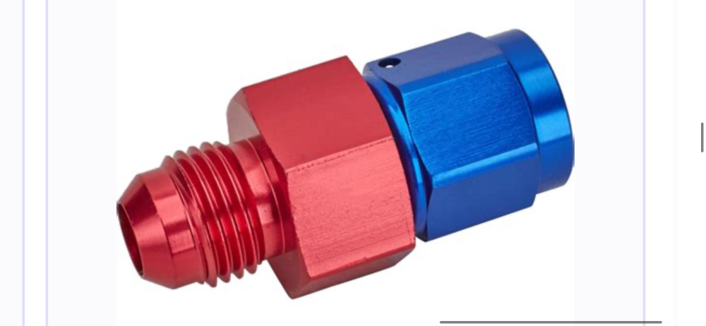
Ideally it will be a metal T threaded between the ip and the nipple fitting. Similar to this one that is red & blue. It will be an accurate reading permanently.

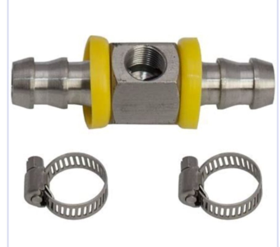
The second choice is to use one similar to the one that has rubber hose on both sides (with the yellow rings) you don’t need the push-lock fitting, just king nipple will work. Buy a 4” long piece of new rubber hose that is sae30r9 between T fitting and the ip inlet fitting. This is easier to find but same price usually. But the short 4” long piece should be replaced every 7 years or so to ensure it isn’t creating an issue with interior deterioration. I share it because it is an option for testing right now but can’t strongly suggest the metal T fitting instead of the double nipple fitting.


IMG_3118.pngIMG_3117.jpeg
 
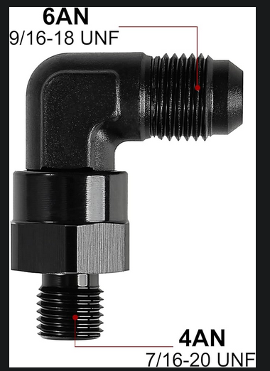
quick and simple, use the second type fitting Will shows. to use the fitting in the first pic he shows, you will need to remove the small 5/16" barb from the IP and replace it with a male an-6 to #4 boss fitting. the 5/16" barb fitting will unscrew from the larger nut on the IP. I will see if I can find the fitting you need online to replace it with. only issue is there is not much room since the inlet hose runs underneath the intake up to the FFM and there is no slack. this is one of the reasons I removed my FFM and ran the inlet hose over the top of the intake.

That inlet hose is a pre-formed hose due to the tight bend in it at the IP. you can't simply replace it with regular fuel hose if you cut it.
 
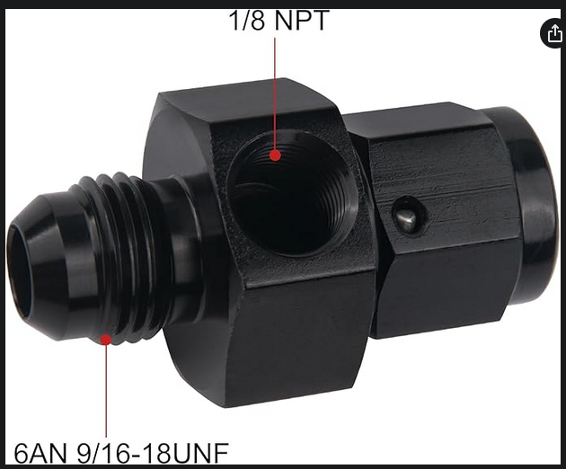
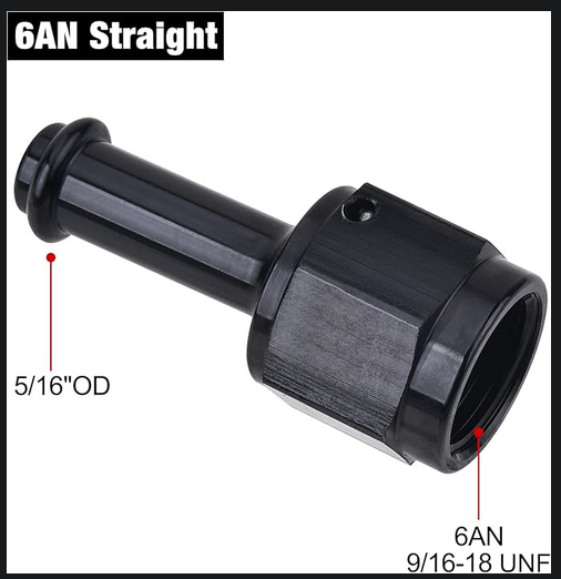
This will fit into the top of the IP and allow you to connect a tee, but will require you to re-route the inlet fuel hose.

1744338951709.png

Then you'll need this tee.
1744339065598.png

Then this to connect to the 5/16 fuel hose and run back to the FFM.
1744339194733.png

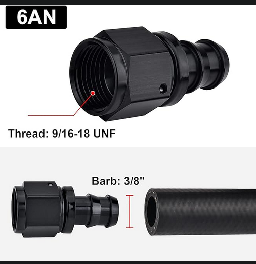
You can use this type instead of the above hose barb connection, but iirc it uses a thicker walled hose similar to trans cooler hose. can't remember the name for it but your local Napa should sell it. it's a much better connection and doesn't need a hose clamp. once you push the hose on, your not pulling it back off without damaging the hose! This is for 3/8" hose as well so if you go this route (much better) you will need to ether modify the FFM (feed the beast mod) or order a new FFM from Leroy already setup for this.
1744339389480.png
 
As an Amazon Associate we earn from qualifying purchases.
Now all of the above I mentioned is meant for a permanent mounted fuel pressure gauge and you do NOT want to use a mechanical gauge with a live fuel line running into the cab unless your looking for a fire hazard!

invest into an electric fuel pressure gauge if you want to permanently mount it. a temporary just to see what's happening and later remove and plug the tee with an 1/8" pipe plug, by all means use a mechanical gauge and run the plastic tube for it into the cab, but heed the warning, use this method only while you diagnose the issue, immediately remove it and plug the tee once diagnosis is complete!

BTW here is the 5/16" inline tee will mentioned for the simple and temporary route.
1744339899311.png
 
As an Amazon Associate we earn from qualifying purchases.
Here ya go @Will L.

 
Back
Top