• Welcome to The Truck Stop! We see you haven't REGISTERED yet.

    Your truck knowledge is missing!
    • Registration is FREE , all we need is your birthday and email. (We don't share ANY data with ANYONE)
    • We have tons of knowledge here for your diesel truck!
    • Post your own topics and reply to existing threads to help others out!
    • NO ADS! The site is fully functional and ad free!
    CLICK HERE TO REGISTER!

    Problems registering? Click here to contact us!

    Already registered, but need a PASSWORD RESET? CLICK HERE TO RESET YOUR PASSWORD!

What did you do with your GMT400 today...or yesterday....

i kinda got lost here,. you have a couple of bad glow plugs/wires,.? but you are changing the pump? sorry i don't quite follow,.?
Glow plug wires is all good. GPs was all good. IP is good. The injectors was all bad. I am waiting for a reply from one of the members about getting him to rebuild the injectors.
The thing I am working on is, I have a spare reman IP that is charged full of diesel fuel. This is a DS4 pump. I want to purge the pump of diesel fuel and charge it with hydraulic jack oil. The diesel fuel will eventually break down and gum the interior components of the pump rendering it worthless in a time of need.
With all of the electronics related to the IP I am finding it difficult to get the IP to flow through the pump and out the injection nozzles.
A reman pump comes charged with a test fluid that does not break down no matter how many years the pump might set on the shelf or bench.
Thats all.
 
I'm not sure how the DS4 pump works but I think it will need to see an RPM signal through the PMD for it to start pumping the oil through it.

not exactly sure what type of signal the CPS sends but this intrigues me to want to build a test bench that would run a IP without the engine sort if for this purpose. I would think if you could somehow rig up something to reproduce the CPS signal without cranking the engine like you have it all setup now, that would for sure have it pumping oil. just having the lift pump sending pressure into the IP, you should be seeing some fluid pushing into the return line as long as the LP has enough pressure.
 
Being as how the intake manifold is removed, I also removed the oil pressure sensor. Went to NAPA and got an extension hose made. 1/4” hydraulic hose with 1/4” male pipe on one end and a 1/4” female pipe on the other end by 28” long.
Screwed a 90* street el into the engine block oil pressure port. Screwed the extension hose into that el and have the female end of the hose hanging about mid firewall.
Next will be to screw the oil pressure sensor into that and have that sensor where it will be obtainable if ever it would start leaking.
First though I need to plug that hose, hook the OP sensor to the air hose through a regulator and have that part of it done.
Next will be to hook the remote start button switch to the started then, turn on the ignition switch, press the start button, rotate the spare IPs shaft K
I'm not sure how the DS4 pump works but I think it will need to see an RPM signal through the PMD for it to start pumping the oil through it.

not exactly sure what type of signal the CPS sends but this intrigues me to want to build a test bench that would run a IP without the engine sort if for this purpose. I would think if you could somehow rig up something to reproduce the CPS signal without cranking the engine like you have it all setup now, that would for sure have it pumping oil. just having the lift pump sending pressure into the IP, you should be seeing some fluid pushing into the return line as long as the LP has enough pressure.
that would be a nice setup. To be able to bolt down and spin the DS4 pump and have it fully functional.
I’m not getting any more done on it today.
Back, legs and hands in enough pain.
I found shims for the injectors. Guess I’ll see what I can find now for nozzles with pintles. I do not want to use chinese nozzles. Not knowing who Bosch is sourcing their nozzles from I’m weary of trying bosch nozzles, injectors too.
Those made in Italy nozzles might be the best thing out there but so far I have not been able to find a source.
 
if the nozzles in your injectors were "new" when they were remaned they might just be carboned up. I would be interested in pulling them apart, dropping all the parts in a ultrasonic cleaner with some b-12 chemtool or some sort of solvent that would dissolve the carbon deposits. then inspect them for wear. slap back together and use the pop tester to see if that made any difference.

I also saw a video on lapping the pintles in the nozzles with some very fine polishing compound to fix the seats for leak down issues. same type of process like lapping valve seats but with a much finer compound.
I did give cleaning them Nozzles and pintles a thought.
It is just too much work to tear one of these trucks down far enough to get the injectors out. I just do not want to take that chance.
With less than 20,000 miles on these BWD reman units I dont want to go through that again. I know that the trucks the state run was way over 100,000 miles and there was never a problem with the injectors. Must be something to say about those original Bosch components.
 
I bet one could easily put together a sort of test bench using an old obd1 pcm making a minature harness connecting all the engine sensors and PMD to it. getting a reostat to fake the engine temp sender and be able to set that at various temps if needed, along with a lift pump to supply fluid. use a little dc electric motor with the right coupling adding someing to mimic the cps attached to it with a motor controller to function the RPMs and have a "redneck" DS4 IP pump stand.
 
I did give cleaning them Nozzles and pintles a thought.
It is just too much work to tear one of these trucks down far enough to get the injectors out. I just do not want to take that chance.
With less than 20,000 miles on these BWD reman units I dont want to go through that again. I know that the trucks the state run was way over 100,000 miles and there was never a problem with the injectors. Must be something to say about those original Bosch components.
True. it is a lot of work to replace the injectors. I wish they were as easy as spark plugs on a old 350 lol not too bad on the drivers, but the turbo side.... forget it. If the turbo was just a little bit further away. Dam those GM engineers LOL
 
German engineers are even worse! while I was putting the Jetta back together, I was laying up under it working on installing the passenger CV axle and the sub frame / lower suspension components I saw the heater hoses up by the turbo ( between the firewall and the sideways engine) they were saturated in oil and muck. even has those plastic junk quick connectors on the heater pipes coming out of the firewall. I am going to have to go back in there to replace the hoses but didn't want to do it now since I didn't know if the car was going to work or not.

the only way to get back in there is to remove the center section of the sub frame that supports the steering rack plus remove the passenger CV axle from the tranny (bolts on to flanges) just to get access to reach up in there for the heater hoses. there is absolutely no way to access them from up top! even if I was to remove the dog bone mount and force the engine to tilt forwards.
 
On the ip getting flushed with oil- it’s far easier to do with a running truck.

On the diy extension hose- remember you have to carry a ground. The steel braided internal ones, the trick is cut the hose 1/2” longer, then 90% of the way a d trim away the excess except a small portion of the braiding to fold under the crimp. Otherwise grab some 14awg wire and add a ground if you aren’t getting signal.

There are many people that run injectors 300,000 miles. They just run poorly. There is no recommendation from gm when to change. We just learned that at 100,000 miles we should replace things like balancer, hoses, etc so we did it at that time also. Like a major service interval. The noticeable drop of performance for injectors is 125-150,000 miles depending on fuel quality. 400,000 miles or slightly over is a normal target life for these engines so it all fit nicely. If a feller knew he was dumping it at 350,000 and was putting on modern high end filtration-then I would say do 125,000 & 250,000, and they would be due again at engine rebuild time.
 
Have a spare lift pump and bolted it to the firewall. It has a + and a - lead to the battery.
The IP has all the wires from the IP mounted to the engine run to it. Get the OP sensor hooked to an airhose fitting with the pressure regulator set at about 60 pounds and that should solve that portion of the problem.
The next step will be to crank the engine to get crank reference signal and then maybe it might open the IP to allow the oil to flow through. About the only other thing I can think of that would mess with the plan is if the crank position signal and the RPMs of the ip dont match and woould then not allow oil to pass through. 🤷‍♂️😹
actually now that I think about it. you shouldn't need to crank it. disconnect your crank position sensor, key on and spin the IP. start out slow and then speed up the IP. I assume your using a drill to spin it. it will take a minute but the PCM will set a code for the CPS and then begin to work off the optic sensor using it for the RPM reference. you might even connect a scanner to the truck and monitor it for the RPM signal. you can also use the scanner to verify your fake oil pressure from the air your feeding it.

if the scanner picks up an RPM signal from the optic sensor, then your fooling the PCM making it think it's actually running. try to keep the rotation around 600 or it might trigger other codes and cause the PCM to shut down fueling thinking it's in a runaway situation.
 
Just be sure everything is disconnected from the IP mounted on the truck including the fuel solenoid. also make sure the fuel line to it is blocked or there is no way the trucks lift pump will feed any fuel to it. this way your insuring that no fuel actually leaks into the engine if that portion is still connected.
 
Just be sure everything is disconnected from the IP mounted on the truck including the fuel solenoid. also make sure the fuel line to it is blocked or there is no way the trucks lift pump will feed any fuel to it. this way your insuring that no fuel actually leaks into the engine if that portion is still connected.
Yes. I disconnected the terminals back at the lift pump. Also, stubs of return hoses that I clamped shut.
Tomorrow I’ll get the OP sensor hooked to air and disconnect the CPS and give that a spin.
I do have a drive adapter for the drill and will get that in motion too.
 
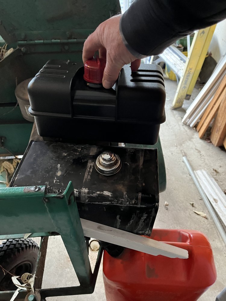
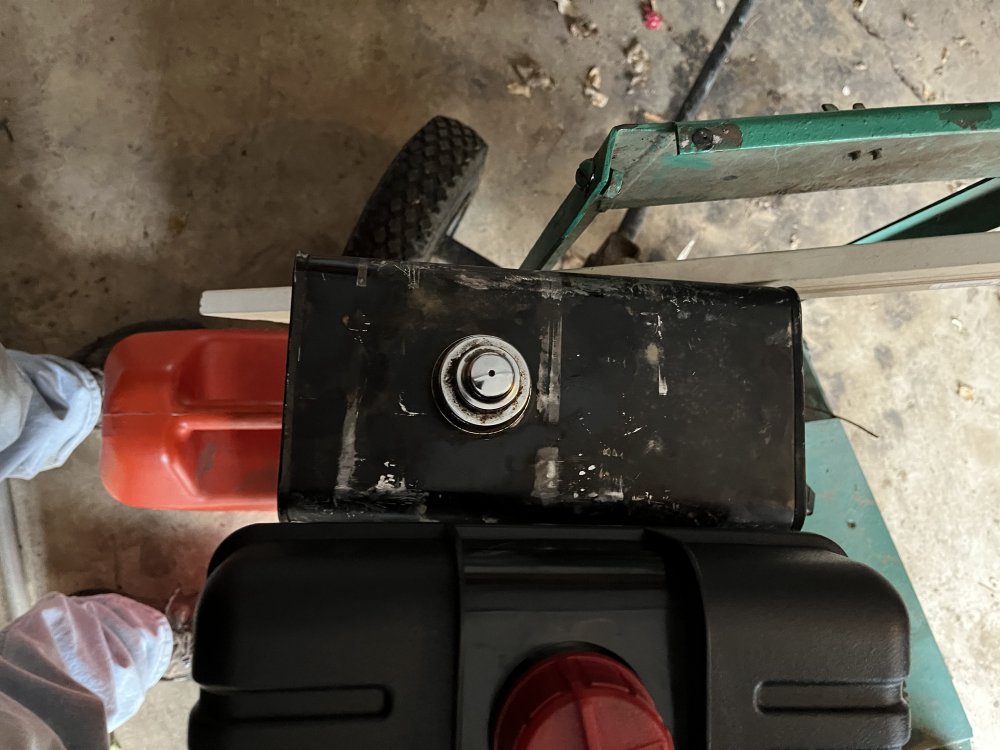
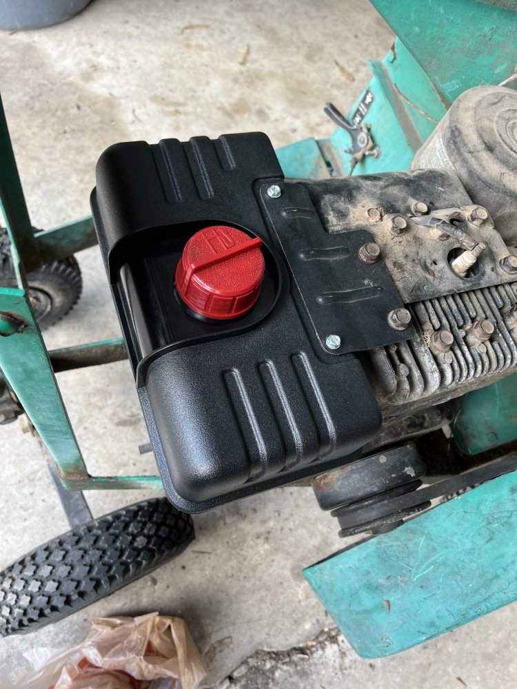
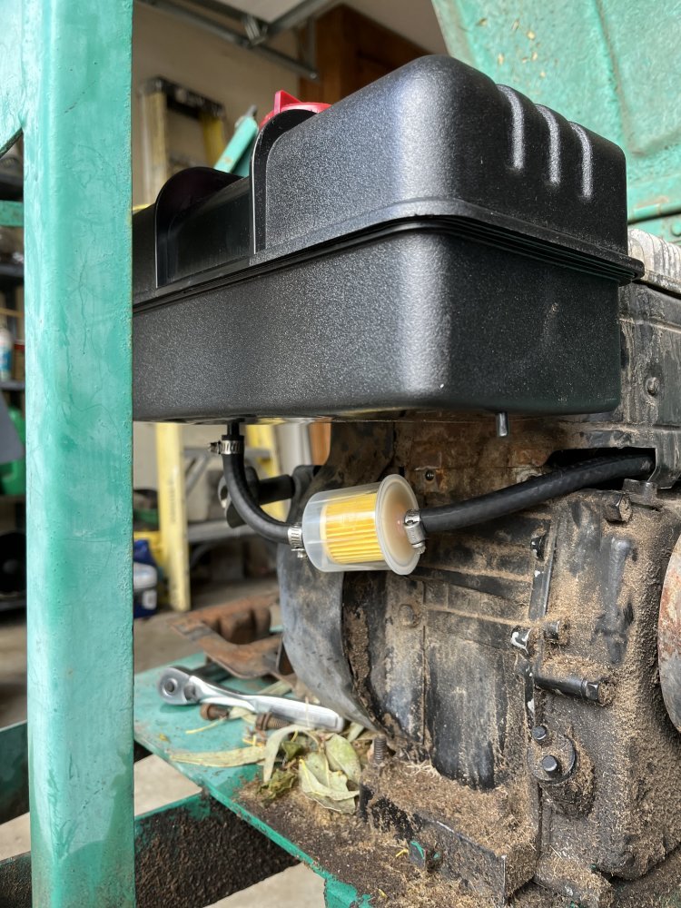
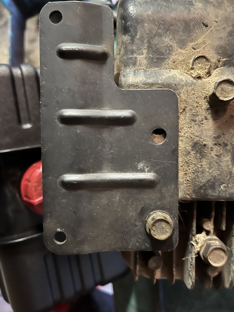
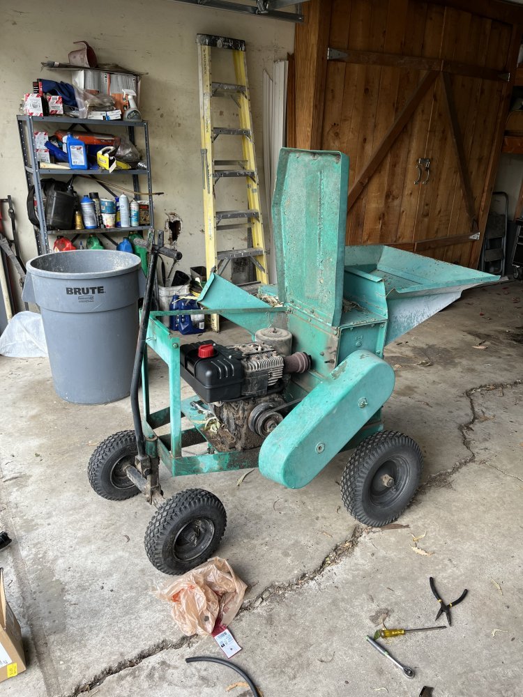
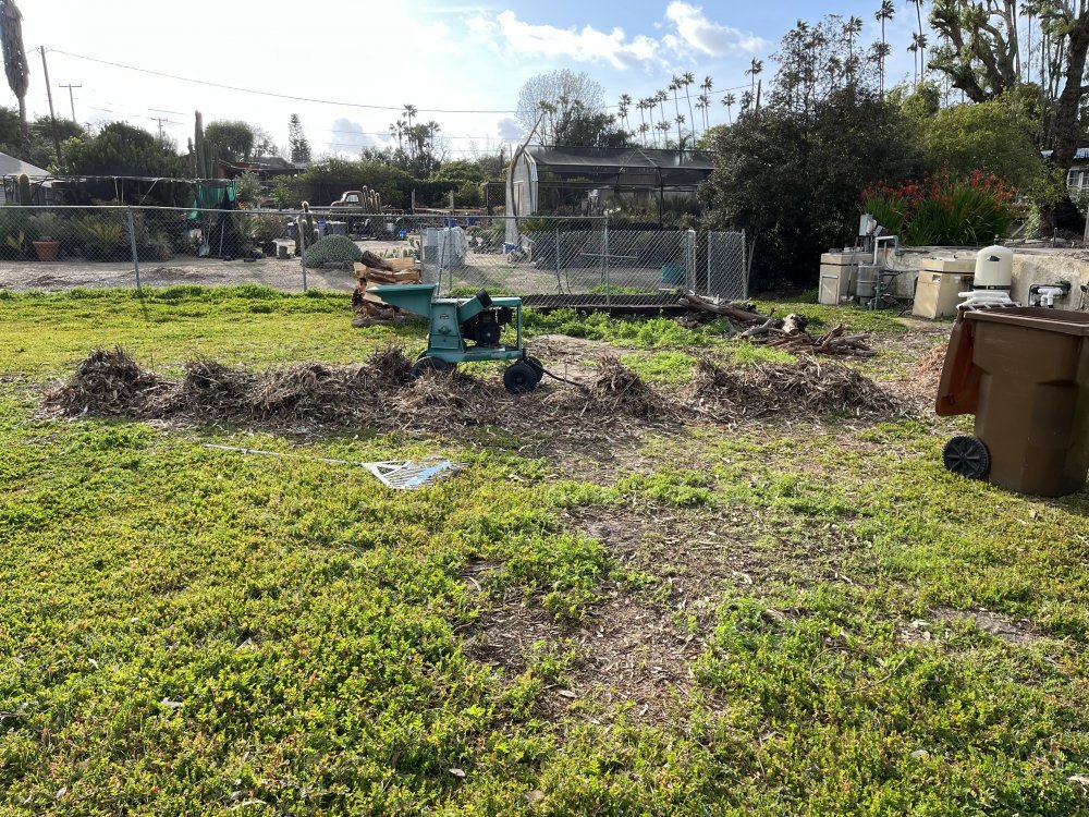
Been using my neighbor’s chipper which quite easily could be 50 years old. It had a steel fuel tank which he had zip tied to a bracket on the engine. Of course those broke, so I used large screw clamps for HVAC ducting and those broke too and knocked off the glass bowl on the fuel filter attached to the tank. It had been glued in place with a grey sealant. The tank does not have bracket mounts attached to it and I did not want to weld some on.

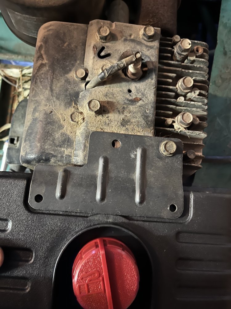
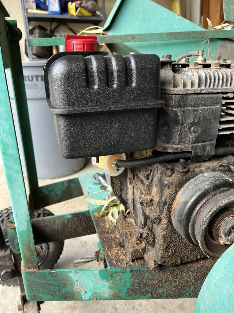
So it was time to go a different route. I ordered a Polyethylene tank and bracket for an 8 hp Tecumseh engine (chipper has an 8 hp Briggs & Stratton). Engine side of the bracket was a close fit, I had to egg out one hole to make it work. I cut the original bracket and use that as a pedestal for the bottom of the tank. I used the chipper most of the day to finish up on the slash from the Eucalyptus tree. Tank did come off once. Engine imparts quite a bit of vibration. Just need to check the screws on the tank side of the bracket every couple hours.358A4AE5-119A-49F4-943E-D7C31C2D2B68.jpegAE881F68-C8C2-447E-BEEB-3D554C028F4B.jpeg28F2EA7B-3457-45D5-A5A8-40B690455A34.jpeg3ABB9006-1083-4345-A31F-E77A353BA203.jpegB05054BB-BEB9-45FB-854B-361F65EA6EAA.jpegAFD1C492-2D2A-4219-BC04-5F7DC876B8B9.jpeg60EF104D-6F4E-43DC-98E6-DDD05D680F8C.jpeg24F21148-D271-4DBC-AC7D-B1DB98DA0009.jpegDF1D9CF5-F7DC-4470-8E95-3CB0E5858EE1.jpeg
 
Been using my neighbor’s chipper which quite easily could be 50 years old. It had a steel fuel tank which he had zip tied to a bracket on the engine. Of course those broke, so I used large screw clamps for HVAC ducting and those broke too and knocked off the glass bowl on the fuel filter attached to the tank. It had been glued in place with a grey sealant. The tank does not have bracket mounts attached to it and I did not want to weld some on.

So it was time to go a different route. I ordered a Polyethylene tank and bracket for an 8 hp Tecumseh engine (chipper has an 8 hp Briggs & Stratton). Engine side of the bracket was a close fit, I had to egg out one hole to make it work. I cut the original bracket and use that as a pedestal for the bottom of the tank. I used the chipper most of the day to finish up on the slash from the Eucalyptus tree. Tank did come off once. Engine imparts quite a bit of vibration. Just need to check the screws on the tank side of the bracket every couple hours.View attachment 79917View attachment 79918View attachment 79919View attachment 79920View attachment 79921View attachment 79922View attachment 79923View attachment 79924View attachment 79925
Locktite?
 
Looks like there is a bolt hole on the block just underneath the tank where you might be able to fasten a lower support to help stabilize it. maybe even use it for a section of strap up and over the top. using some aircraft type bolts in the top two fastening the tanks to that bracket so you can safety wire the bolts from loosening too. since there going into a plastic tank they can't be that tight so the safety tie wire will help keep them into place.
 
Looks like there is a bolt hole on the block just underneath the tank where you might be able to fasten a lower support to help stabilize it. maybe even use it for a section of strap up and over the top. using some aircraft type bolts in the top two fastening the tanks to that bracket so you can safety wire the bolts from loosening too. since there going into a plastic tank they can't be that tight so the safety tie wire will help keep them into place.
I used the supports from the original bracket under the tank, adding marine poly board as spacers, which worked. Pics tomorrow.
 
Back
Top