• Welcome to The Truck Stop! We see you haven't REGISTERED yet.

    Your truck knowledge is missing!
    • Registration is FREE , all we need is your birthday and email. (We don't share ANY data with ANYONE)
    • We have tons of knowledge here for your diesel truck!
    • Post your own topics and reply to existing threads to help others out!
    • NO ADS! The site is fully functional and ad free!
    CLICK HERE TO REGISTER!

    Problems registering? Click here to contact us!

    Already registered, but need a PASSWORD RESET? CLICK HERE TO RESET YOUR PASSWORD!

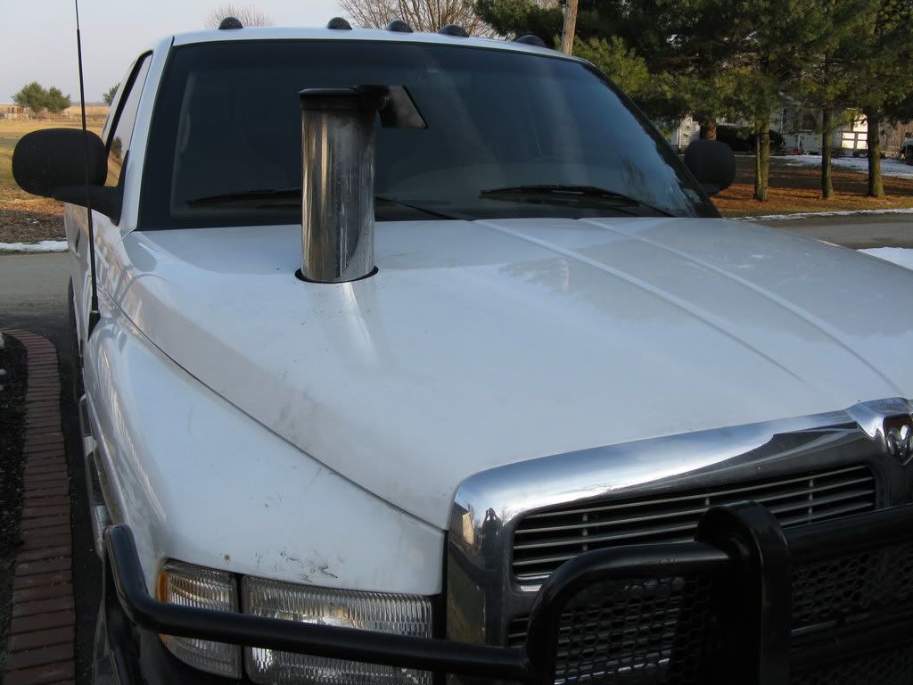
Hood vents... Maybe not...

I think we mostly agree here, but your drawings have the pluses and minuses switched. Bernoulli's Law dictates that when the velocity of a flow decreases the pressure increases. Think of the windshield as an air dam. The flow of air over the hood pushes against the windshield and forces the air to slow down and increases its pressure. The high velocity air that flows up and over the windshield must necessarily be lower pressure. Using the snowflake example you used earlier, if the air close to the glass was lower pressure than the air flowing over the windshield the snowflakes would be pulled into the low pressure region and impact the glass. The fact that the snowflakes push away from the glass is further evidence that the pressure in that area is higher than in the high velocity flow region further away from the windshield. Another example is the effect of a large rock in the middle of a flowing stream. If you look closely you can actually see that the water level on the upstream side of the rock is higher than water that is flowing around either side. The flow of water is pushing against the rock and creating a high pressure zone which actually pushes the surface of the water upward.
 
I think we mostly agree here, but your drawings have the pluses and minuses switched. Bernoulli's Law dictates that when the velocity of a flow decreases the pressure increases. Think of the windshield as an air dam. The flow of air over the hood pushes against the windshield and forces the air to slow down and increases its pressure. The high velocity air that flows up and over the windshield must necessarily be lower pressure. Using the snowflake example you used earlier, if the air close to the glass was lower pressure than the air flowing over the windshield the snowflakes would be pulled into the low pressure region and impact the glass. The fact that the snowflakes push away from the glass is further evidence that the pressure in that area is higher than in the high velocity flow region further away from the windshield. Another example is the effect of a large rock in the middle of a flowing stream. If you look closely you can actually see that the water level on the upstream side of the rock is higher than water that is flowing around either side. The flow of water is pushing against the rock and creating a high pressure zone which actually pushes the surface of the water upward.

Bernoulli's Priniciple can be observed clearly when there is in no laminar flow involved as in a simple Venturi flow meter (VenturiFlow.htm), in an environment where the fluid is enclosed. In our case, there is laminar flow, and the fluid (air) is not enclosed. Again, the speed and shape of the vehicle have much to do with when laminar flow will form, and when and where high/low pressure zones occur.

What was not considered was that the air was already slowed down before it reached the hood:
-- the front of the vehicle slows and compresses the air (increase in pressure per Bernoulli) in front of it causing most of the air still coming towards the vehicle to separate and flow (now laminar) over/around the vehicle
-- the compressed air in front of the vehicle continues to flow over the hood (and the laminar airflow over it) where it begins to accelerate (decrease in pressure per Bernoulli)
-- the decompressed air decelerates as it approaches the windshield (increase in pressure per Bernoulli), creating another high pressure zone together with the eddy currents (the eddy currents form because of the large volume created between the laminar airflow and the hood's surface)
-- the compressed-again-air goes over the top of the vehicle, it accelerates (decrease in pressure per Bernoulli) towards the rear of the vehicle, etc.
-- all the while, the separated/laminar airflow does not touch the vehicle's surface...

The plus and minus signs were simply indicating where along the hood's surface the pressure goes from high and low.

In your example of a rock in the flowing stream, the water flows over the rock because of the water's momentum -- the water molecules bunch up and push upwards because they have nowhere else to go. Also, because of water's incompressibility (typical of almost all liquids), pressure differrentials in that situation are infinitessimal to the point that they are negligible.

Regards,
Franko
 
here is the only vent that makes sense :

131_0702_12_z+chevrolet_avalanche+front_view.jpg


;-)


found another one :

HoodStackFrontcoroner.jpg
 
I know somebody that rigs up clear tubing with water/food coloring to test differential air pressure when locating hood scoops/cooler vents on his race cars.

Fixes the tube end at the location he wants to test pressure with #9 wire & tape; then runs the tubing into the interior where it's taped to a little chunk of yardstick taped vertical. He says it's only a rough indicator & you have to drive on the level & a steady speed so inertia doesn't affect the water levels.

Haven't tried this myself.

Another way to test this stuff is to pick up a magnehelic differential pressure gauge. They're used for measuring small pressure differences accurately & can often be found inexpensive on ebay.

http://cgi.ebay.com/Dwyer-Magneheli...emQQptZLH_DefaultDomain_0?hash=item3efca13a9f

Franko - do you have a rough estimate of the scale the pressure differences at the base of the windshield would be? to get an idea of what scale magnehelic would work best for this purpose.

I borrow a friend's to test if my project's air filter flow capacity is adequate at highest airflow demands. The pressure difference btwn before & after the filter at full load/WOT indicates how much restriction the filter/air intake is causing.

I believe the 1" to 3" H2O scale would be sufficient for your purpose -- we're talking about low pressure differentials (much like ventilation systems). The question, then, is where to situate the ends of the hoses because you want to measure pressure differences... differences where? One end, obviously, on top of the hood... the other end should, then, be in the engine compartment, not in the passenger compartment! Ideally, the hose ends should be located on the same spot of the hood: one over, the other under.

I bought a couple of the magnehelic gauges off eBay a couple of years ago (liquid filled) to measure pressure differential before and after the oil filter and fuel filter -- same principle as for the air filter. I ended up installing small (~1.25") liquid filled oil pressure gauges before and after and eye-balled it... worked just fine. Am thinking of installing similar for the fuel filter (lower scale)...

Anyhow, here's a link for "The Basics of Downforce" that discusses ground effects, downward forces, aerodynamics, etc. It starts off with "Typical Airflow Around a Car" which goes into high pressure air in front of the vehicle and in front of the windshield... it's pretty good reading...

http://www.superhachi.com/theory/downforce/

Regards,
Franko
 
Just a thought guys. Cowl induction is good for getting cool air into the intake with the setup sealed for this purpose, because of the pressure area at the windshield base. I also believe that with the cowl opening exposed directly to the engine compartment, the air pressure forced through the grille would be greater than that at the windshield base. If this is the case, then it would act as anextractor for the under-hood heat, which is the intended purpose for this discussion. If this is the case, then would it not hold true for louvered vents like Franko's. Don't have any hard data, just guesstimates.
 
Last edited:
since people here are actually quoting Bernoulli and such could someone please throw out there at which speeds aerodynamics come into account. because i hate to say this, but we are driving around trucks with the cw value of barn doors (no, not laying flat on the ground) but even that does not matter at these speeds and the discussions of pressure areas and aerodynamics is a bit over the top i would suggest.

next thing you know someone will actually sell naca air inlets for the hood.....
 
Thanks much for the link. Embarassingly, I hadn't stopped to think about where the liquid/tube setup was referencing pressure (in the interior), but makes perfect sense.

In relation to my turbo project, I'm thinking of relocating my batteries to inside a cross-toolbox in the truck bed, so I can fab a much straighter intake path & maybe even gain a slight ram air effect at hwy speeds.

The thought would be to build an airbox behind the pass side headlight, with an opening/inlet several inches below the air filter around the height of behind the pkg light & stock air inlet hole thru the radiator header panel. Having the filter somewhat above the inlet would help limit rainwater exposure to the filter element.

Figure the airbox passage(s) thru the rad header, etc., opening would have to be well segregated from the radiator/bumper openings to contain any positive pressure/ram air.

Anybody have any experience doing something like this on these trucks?
 
since people here are actually quoting Bernoulli and such could someone please throw out there at which speeds aerodynamics come into account. because i hate to say this, but we are driving around trucks with the cw value of barn doors (no, not laying flat on the ground) but even that does not matter at these speeds and the discussions of pressure areas and aerodynamics is a bit over the top i would suggest.

next thing you know someone will actually sell naca air inlets for the hood.....

If you use Bernoulli's formula and 0.45 for the Coefficient of Drag for an SUV (see table below), you should get the value of 25-30 mph...


Of course, I'm just f***ing with you... That was just a guess...):h

Cd Object or shape
2.1 rectangular box
1.8~2.0 eiffel tower
1.3~1.5 empire state building
1.0~1.4 skydiver
1.5~1.6 skydiver, naked
1.0~1.3 person standing
0.9 bicycle
0.7~1.1 formula one race car
0.6 bicycle with faring
0.7 bicycle with fairy
0.5 sphere or suicide bomber's head
0.7~0.9 tractor-trailer, heavy truck
0.6~0.7 tractor-trailer with faring
0.35~0.45 suv, light truck
0.25~0.35 typical car
0.05 airplane wing, normal operation
0.15 airplane wing, at stall
0.05 airplaine wing, at crash
0.020~0.025 airship, blimp, dirigible, zeppelin

Note that the F1 race car's Cd is higher than an SUV's... it's that darned air scoop... (and exposed tires...). Also, I didn't know that the Eiffel Tower and Empire State Building raced each other, occasionally...
 
yeah and they actually move at a speed where any of this matters !!!

;-)

You've hit the nail squarely on the head with your :thumbsup: sarcasm...

F1 race cars sacrifice their aerodynamic drag coefficient for aerodynamic downforce which gives them the ability to take turns at extremely high (relative to other street/race vehicles) speeds. In fact, F1 race cars are designed, primarily, for that purpose, high speed cornering (design for maximum speed is secondary but, nevertheless, remains critical).

Just to give you an idea of the downforces involved, an Indy race car can produce a down force equal to its weight at 120 mph, whereas an F1 can produce a down force equal to its weight at 80 mph, double that at 120 mph, and triple that at the straightaway speeds of over 200 mph.

F1 teams continue to develop aerodynamic features that generate vortices underneath the vehicles which produce a low pressure zone that results in atmospheric pressure adding to the downforce -- by balancing the aerodynamic design "formulae" between drag and downforce, they can gain higher speeds in the straightaways AND in the curves.

Regards,
Franko
 
Last edited:
Yeah, I've often thought it would be neat to see a race track where part of the course was upside down! How cool would that be... racing along like normal, then the track inverts! Better keep 'yer speed up!

------

I'm really enjoying this thread - enjoying reading the discussions. I understand pressure differentials, Bernoulli's law, etc. But still just a bit hazy about what's actually going on at the hood/windshield. I thought I had it after the first picture, but the further discussion muddied it for me.

Let's see if I've got right:

There's a high velocity (low pressure) layer of air moving well above the surface of the hood (likely forces higher than normal because of the deflector). Underneath that layer would be high pressure which continues to keep that upper layer... well, up. This lower layer is also moving, but moving forward - and not as fast as the upper layer... hence the upper layer (low pressure) and lower layer (high pressure).

The upper layer hitting the windshield causes eddies, which may further enhance the layer separation? I.E., causing that upper layer to stay even further away from the windshield and making a smoother transition from the hood angle to the windshield angle?

Would the sun visor... possibly create a pocket of high pressure, similar to the cowl area?

Sounds like you've got it. I'd guess that the visor would increase the size of the high pressure zone in front of the windshield since it is obstructing and therefore slowing down the flow of air going over the top of the windshield.
 
It think more vents the better. Air will move through them. I also think the turbo can easily suck in any open air source, forwards facing, or rear facing, high or low pressure. I think the temperature of the air is more important than a ram/pressure orientation for a turbo application.

Ramair is great for N/A, but the turbo's can already suck all the air they need, shortest, freshest, non fan-washed air source the better I think. Sure a little ram may help, but don't expect it to spin the turbo for you :)
 
..The 2nd generation Trans Am had heat extractors in the front fenders. Air flowing over the vents would pull the heat out of the engine compartment.

You mean, like this:

DSC03877a.jpg


Just a little project I have underway..................;)

If you look under the hood in the back corners beneath the hood hinges, you can see openings that "vent" underhood air into the fender/door joint area.

Fans would just be a needless "complexity" on the airflow scheme. Hot air will radiate out at a stop, airflow over the scoop will draw it out at speed.
 
Last edited:
You mean, like this:

DSC03877a.jpg


Just a little project I have underway..................;)

If you look under the hood in the back corners beneath the hood honges, you can see openings that "vent" underhood air into the fender/door joint area.

FAns would just be a needless "complexity" on the airflow scheme. Hot air will radiate out at a stop, airflow over the scoop will draw it out at speed.

I saw the same on a Trans Am and then the 2 different year Camaros had different vents too.
 
Doesn't look bad at all. Dad had to do that with his '75 to help remove heat from under the hood. He used the louvered ones from the older Z28. Sitting at a stop sign, heat can be felt boiling out of the vent.
 
You mean, like this:

DSC03877a.jpg


Just a little project I have underway..................;)

If you look under the hood in the back corners beneath the hood honges, you can see openings that "vent" underhood air into the fender/door joint area.

FAns would just be a needless "complexity" on the airflow scheme. Hot air will radiate out at a stop, airflow over the scoop will draw it out at speed.

What did those come off of??
 
What did those come off of??

They appear to be '70-'81 vintage Trans Am fender vents.
I looked under the hood, and the factory cutouts inside the fender, right ahead of the hood hinges as mentioned, look like a perfect position for those vents in the pic. Almost like the general designed them for just that purpose.

I looked at the '78-'79 and '80-'81 Z-28 vents, they look a bit larger. Not sure they would fit as cleanly as those in great white's pic. Trucks without the factory fender flare may have the room needed for the Z-28 vents however.
 
Back
Top