• Welcome to The Truck Stop! We see you haven't REGISTERED yet.

    Your truck knowledge is missing!
    • Registration is FREE , all we need is your birthday and email. (We don't share ANY data with ANYONE)
    • We have tons of knowledge here for your diesel truck!
    • Post your own topics and reply to existing threads to help others out!
    • NO ADS! The site is fully functional and ad free!
    CLICK HERE TO REGISTER!

    Problems registering? Click here to contact us!

    Already registered, but need a PASSWORD RESET? CLICK HERE TO RESET YOUR PASSWORD!

Electric Fan clutch

I was just going to ask what controller @CursedH1 was running, the pic looks like a different controller that I run on mine. ether way the hayden controller I have only has one dial to adjust when the fan turns on. and mine does stay on for a bit (I forget what temp is turns off) Now something to consider.. these viscous fans don't release as soon as the power is turned off. it does take some engine RPM to break them free after the controller turns off. at least that has been my experience.
 
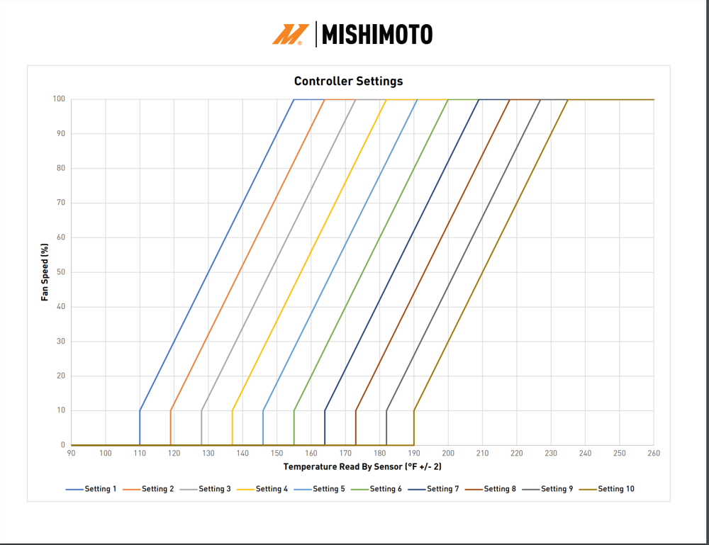
The picture of the wire/harness is the controller box. Its a Mishimoto PWM controller. It has a dial in it to adjust the temp but its nigh impossible to really see where its set on their less-than-helpful chart of the settings. As for the location on the p/s head... thankfully I've got that center-mount turbo on the H1. That hole is where the H1's ECM temp sender probe is located (pic below). This is where I was thinking of putting in a 90degree tee but again, I'm concerned about coolant flow past the sender.

I've been tossing around the idea of retrofitting the HMMWV fan clutch system on my H1 - unfortunately I've already got a milemarker hydraulic winch plumbed into that system and I donno if my PS pump is up to the task.

1717538273194.png
 
So use the drivers side hole.
Thats what I was wondering - if there even was a driver's side hole lol. I just went down and looked and I didn't see anything immediately available in front of the windshield... was thinking it may be close to where the t-stat housing is attached but there's a big honkin A/C compressor in the way.

Could you give me an idea of where the d/s hole is?

Thanks!
 
Personally I think the issue is more with the capabilities of the controller, specifically the ramp curve of the Mishimoto.
In my use case, I am running a Flex-a-Lite 31163 Variable Speed Controller.
The ramp curve starts at 60% duty at set temp and increases to 100% duty 10 degrees F later.
It takes approx. 30 sec to go from unlocked to fully locked (in my case from 60% to sub-70% duty cycle based on temp increase).
Cool down and subsequent unlock takes approx. 90 sec after the controller shuts off (drops below set temp).
BTW: I am reading the fan speed rpm off the hall effect sensor in the fan so I can see how the fan behaves before I actually hear it.
The Mishimoto might be great for an electric fan, but an EV fan is basically all on or all off (more function of the rate of how quickly the fluid heats before it begins to couple). A 45 degree F span from 10% to 100% (or 30 degree F from 10% to 70%) would be a hard pass in my case.
I don't think using a controller with a variable duty cycle will work with the electroviscous fan clutch. these units don't like anything less than 12v. all the controller is powering is a heating element which in turn heats the front of the fan clutch to turn it on. the clutch it's self has no electronics.
 
I don't think using a controller with a variable duty cycle will work with the electroviscous fan clutch. these units don't like anything less than 12v. all the controller is powering is a heating element which in turn heats the front of the fan clutch to turn it on. the clutch it's self has no electronics.
Technically speaking the clutch itself supports PWM applications since the wires on the harness are there to give fan speed feedback to the theoretical ECM in an OEM situation.

I'll take a look at the Flex-a-Lite 31163 Variable Speed Controller.
 
I feel like I need to further explain the Mishimoto controller choice. First of all it had a lifetime warranty. That by itself was a major selling point. Secondly it seemed to be the only one willing to advertise adverse condition operation, meaning it had some level of water resistance. Where I have to mount this thing is on the washer reservoir right above my d/s tire. All kinds of road crap gets flung up there, and water of course gets splashed up in that area.
Lastly the entire idea behind a PWM controller was to eliminate the temperature pogo-stick effect on the H1's at highways speeds. Due to the shape of our bodies, the H1 (and HMMWV's) create a pressure bubble that sits right over top of the hood when you go any faster than 55mph (the designed top speed of the HMMWV). All of this was discovered in an effort that @Will L. helped AM General with. This causes almost no air to flow down through the top of the hood grate into the cooling stack at speed... indeed the only times we H1's really have a problem with cooling is when we're doing 70 down the highway. What ends up happening in the OEM thermoviscous setup is that the coolant heats up the radiator stack which then triggers the clutch to engage at a certain, undefined temp. The fan runs and almost immediately (within 30 seconds) cools the stack down and it shuts off. Well, the coolant just heats back up again, rather quickly usually... then we're back to the fan cutting back on again.
The hope was that with the PWM controller, the fan clutch/controller would be able to find a "sweet spot" where the fan stayed engaged at a certain percentage and kept the coolant between 195 and 205. It would keep that coolant from bouncing up and down constantly while going down the highway. Unfortunately I don't think the fan clutch has the operational ... sensitivity ... aka the ability to quickly engage and disengage... to be able to do this.
 
Thank you for the explanation. This helps :) what I'm getting at this is instead of a on/off fan. the PWM controller should be able to have the fan come on (for lack of better words) slow so not to be fully locked but create some resistance in the clutch to draw in just enough air to keep things in check. as temps climb the controller will increase PWM signal making the fan come on harder but still not be fully locked in.

This could actually work with how a viscous fan clutch works. a normal one has a coiled metal doohdad that with heat turns the valve in the clutch.
with the electro-viscous clutch the pwm controller would have to be tweaked to send just enough pulses of voltage to heat up the filament making the "doohdad" to only turn the valve just so much.....

Yeah my wording isn't the greatest but you get the idea.
 
Normal the bimetal strip just closes or opens a valve that traps the silicone fluid on the force tract and that locks or unlocks it.

The electric ones opens the valve, lets in some fluid and closes the valve. It gets hotter and it opens for longer time period so more gets in causing more percentage of lock up. In multiple steps until finally all the fluid gets in and gives maximum lock up.

 
From what I have seen in my application, the actual coupling of the clutch follows a logarithmic progression.
Based on my Flex-a-Lite controller (60% duty cycle), 2000 RPM engine speed, 200 RPM initial fan speed (2500 RPM at max coupling), the first 10 sec is very slow (10-30 rpm/sec --> 400 RPM). The next 10 sec is about double the speed (40-80 rpm/sec --> 800 RPM. The last 10 sec is a very rapid climb to 2500 RPM --> max coupling.
The decoupling takes about 90 sec and follows the reverse progression going down, just three times slower.
Finding that sweet spot will definitely take some effort, experimentation, and most likely would require a custom built controller (Arduino, Raspberry Pi).
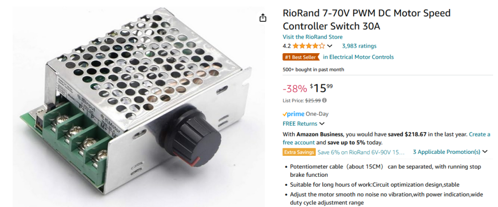
From an experimentation perspective, one can start with a 12VDC Manual PWM controller to see if one can find that sweet spot (relatively inexpensive to set up - most likely less than $20 to implement).
1717731057109.png
 
Just wanted to follow up on my experience so far.

The Mishimoto controller is working but as others have pointed out, isn't ideal. I have it set at a point where the highest temp it kicked in at was 208'F (The H1's t-stats don't fully open until 212'F OEM, mine start to open at 180'F) under a full 15psi of boost - HOWEVER, the fan does NOT disengage unless the temp drops into the low 170's for extended periods of time. When it was 85'F outside, with the A/C on the truck was hovering around 178-181'F but the fan stayed engaged the whole time. I'd prefer that at that temp, the fan wasn't engaged. When the fan is engaged, the truck won't get over 181'F no matter how hard or long I push it.

I did get the Flex-a-lite controller - however the temp probe did not thread into the tstat housing because ... the probe was too long (I feel its struggle). The mishimoto probe doesn't work with the Flex-a-lite controller - so I jammed the flexalite probe into the radiator right where the upper hose enters and did some bench testing with the controller. Its not ideal, but the aforementioned driver's side hole is being used by a factory sensor (I seem to have two sensors at least). Ordered a weathertight project box to mount the flex-a-lite controller in and will do that later this week. Have to do some towing later this week so that'll be a good test of the system.
 
I will have to check what temp mine turns off, but I have the hayden fan controller with a temp probe that uses a 1/8" npt thread. I drilled and tapped a hole on the crossover for it. mine comes on at slightly over 200 degrees (202 or something like that) and will turn off at just under 200.

I will get you the hayden part number if you want it, iirc it should show the degree differential at which it turns on and off.
 
why are you using the crossover?

The hottest place is the rear of the motor, by the time the crossover shows high temp the rear is way hotter..
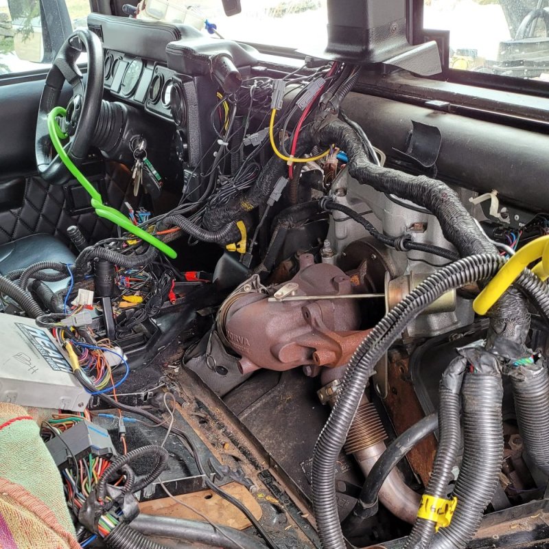
Really because this is the most accessible area, and also because I don't really need the fan to kick in before the t-stats open anyways. Getting to the rear of the engine on the H1 involves ripping out about a third of the interior so if there's any alternative to not doing it, I try not to.

This is why I was rather conservative with setting the engagement temp based off of the temp at the front of the engine - realizing that whatever I'm measuring up front, its hotter in the back.
 

Attachments

  • IMG_20210228_135545_199.jpg
    IMG_20210228_135545_199.jpg
    282.9 KB · Views: 4
I still say on a pickup- controlling the fan at the thermostat makes sense. Having a gauge at the right rear head you read while driving makes sense. I was thinking of over engineered set up of audible alarm and flashy led for it there @220.
 
Back
Top