• Welcome to The Truck Stop! We see you haven't REGISTERED yet.

    Your truck knowledge is missing!
    • Registration is FREE , all we need is your birthday and email. (We don't share ANY data with ANYONE)
    • We have tons of knowledge here for your diesel truck!
    • Post your own topics and reply to existing threads to help others out!
    • NO ADS! The site is fully functional and ad free!
    CLICK HERE TO REGISTER!

    Problems registering? Click here to contact us!

    Already registered, but need a PASSWORD RESET? CLICK HERE TO RESET YOUR PASSWORD!

A military rebuilt 6.5

Now as far as build details go, I was able to mock it up and verify pushrod lengths and valve-to-piston clearance.

My modded lifters that I tack welded to make solid didn't work. I had to keep the tacks small to make sure everything still cleared and using a MIG it just wasn't enough weld. If I had a TIG this would have worked, but I haven't reached that level of cool yet.

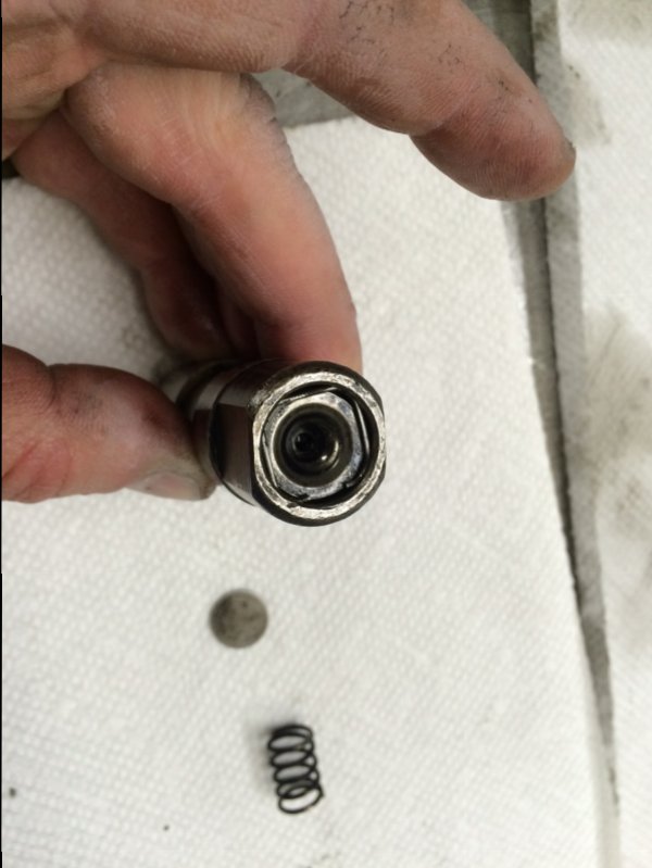
So Plan B: I had read of people disassembling lifters and installing small washers to take up most of the internal space and then filling the rest of the void with JB Weld before reassembling the lifter. Once the JB Weld set the lifter was solid. I figured this would be the way to go. I disassembled a lifter to start figuring out what size and how many washers I would need. For some reason I decided to put the piston in the lifter upside down just to see what that did clearance-wise....to my amazement, it was the perfect configuration to make a solid lifter!!! With the spring and shim removed from the lifter and the piston installed upside down, the lifter cup JUST fit back in and the clip just barely fit back in the groove! This is amazing to me and hopefully helps other people out when trying to check cams.
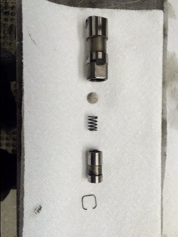
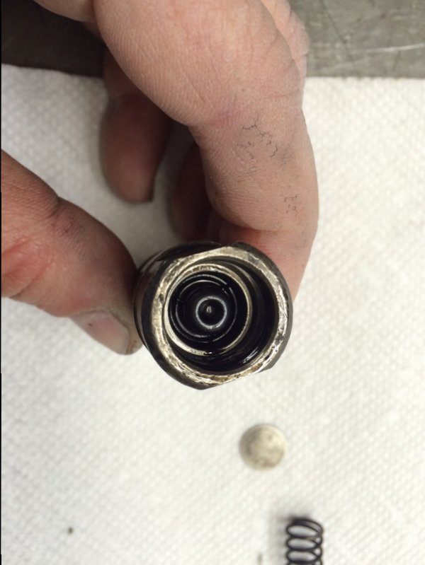
Lifter1.jpg Lifter2.jpg Lifter3.jpg
 
So with the lifters solid I could carry on. I had 2 length checking pushrods. With the rockers installed I adjusted the pushrods until there was zero lash. This gave me the following pushrod lengths:

Intake: 8.760"
Exhaust: 8.728"

Since the Delta cam I am using had a reduced base circle grind on the Intake lobes, it made sense that the zero-lash Intake pushrod was longer. I then measured a stock pushrod, and to my amazement it was exactly to standard specifications (8.824"). I had read that there was a lot of variability in stock pushrod length. I didn't measure the whole set so maybe I just got lucky, but since I wasn't going to get 16 pushrods with pushrod length optimized for each lobe/valve configuration, there wasn't any use to me checking all 16 pushrods anyhow.

Given the zero-lash pushrod lengths, and the stock pushrod length, I could calculate preload for both Intake and Exhaust:

Intake: 8.824 - 8.760 = .064"
Exhaust: 8.824 - 8.728 = .096"

I called Delta cam with these numbers and they said those preload numbers were well within spec so it wasn't necessary for me to get custom pushrods. Amazing! Something I didn't have to spend money on for this build!!

Sorry I don't have any pics of the pushrod length checking :oops:
 
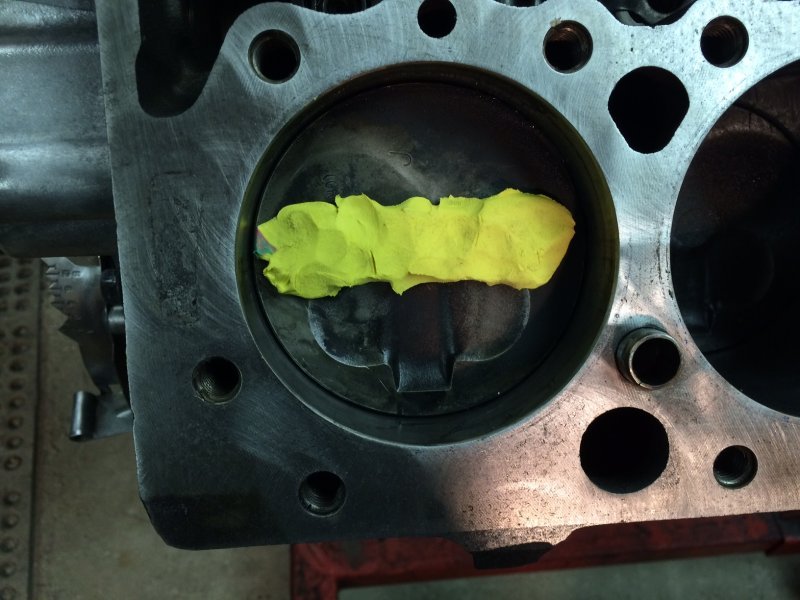
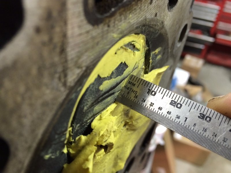
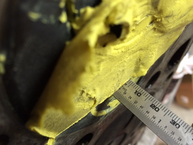
And finally, I have checked my piston-to-valve clearance. I did this a couple times. The first time, I used a modeling clay type substance from Crayola that I found at the grocery store. It was no good. It was squishy and didn't give reliable results. So I did it again, but this time with true modeling clay. I put a chunk on the piston and then rotated the engine over by hand about 5 complete revolutions. I found that I have about 4/64" clearance for the Intake valve and about 7/64" clearance for the Exhaust valve. This works out to about .063" for Intake and .109" for the Exhaust...these are both good values for clearance so I feel comfortable with my specs.

I should note that my particular combo also has stock height heads and block and I'm using +.010" head gaskets, so somebody else's specs could be different, I would check every time a different cam is used.

Clay on piston.jpg Clay Intake.jpg Clay Exhaust.jpg
 
Once I had verified clearances I installed the heads. I used Loctite Blue on the head studs. I applied the Loctite liberally to the threads of the ARP stud and also a squirt into the threaded hole in the block. I then installed the head gasket and head and began torqueing. The first head went fine. The second head I did the same process, but I was delayed between when I installed the head and when I started torqueing the nuts. When I torqued the nuts I felt a weird movement while going through the process. I later figured out that it was likely the stud turning....since there was a delay, I figured that the Loctite had started to set, but not fully, and when I torqued the nuts I broke the Loctite loose. So last night I disassembled the heads again. I found that 6 of the studs on the second head weren't set as well as the others. Those 6 I was able to turn out with the Allen bit at the top of the stud, but the others I had to remove by double nutting. I wasn't able to turn out any of the studs on the first head with the Allen bit, so those had all set correctly. I decided to not disturb the ones on the first head since they had set correctly, but I am redoing all of the second head studs just to be safe. This time I will make sure there isn't a delay between head installation and torqueing the nuts.
Heads installed.jpg
 
Man more damage than you thought that sux.

Yeah, pretty disappointing to see for sure. I was a bit depressed when I found the damage to be sure. I have worked through that though and I am back to being upbeat about getting this thing on the road!
 
Talked to HS this morning. They have 3 sets of spacers in stock ready to mail today. Jay has spoken for one set, do you want the second?
If you can return to them your old ones it will speed up the process for the next guy.
Sorry you had the problems in the first place, but if you had not we would have not known the issue with the binding rockers because I would have just run mine too.
So, again anyone that has bought these rocker arm sets from me and needs the new spacers let me know asap and I'll have HS get new one to you.

Nate thanks for posting the pictures, if anyone wants to see the videos of mine go here http://www.thetruckstop.us/forum/th...-manifold-group-buy.40875/page-17#post-497405
 
Talked to HS this morning. They have 3 sets of spacers in stock ready to mail today. Jay has spoken for one set, do you want the second?
If you can return to them your old ones it will speed up the process for the next guy.
Sorry you had the problems in the first place, but if you had not we would have not known the issue with the binding rockers because I would have just run mine too.
So, again anyone that has bought these rocker arm sets from me and needs the new spacers let me know asap and I'll have HS get new one to you.

Nate thanks for posting the pictures, if anyone wants to see the videos of mine go here http://www.thetruckstop.us/forum/threads/banks-sidewinder-exhaust-manifold-group-buy.40875/page-17#post-497405

Good to know they have the spacers in stock. Yes, I will take the second set of spacers. I talked to them on the phone and sent my video to them. I haven't heard back yet, but you and I are talking to different people. I will definitely send my spacers to them if it helps them get ready for the next guy. Thanks Leroy.
 
Wow Nate, those are some tuff breaks on the rockers, and turbo. :eek: At least your getting it taken care of. I like the way your taking your time, and doing it right, even if it means taking the heads back off to redo the locktite. :D Fantastic work Nate, and this should turn out to be one fantastic 6.5.:)

Matt

Thanks Matt. Since most of my problems were due to coolant in the oil, I wasn't going to risk it again. When I've put engines together in the past, I've always just slapped the parts together. This is the first one where I've really checked everything as it's gone together...it's more time consuming, and honestly not a whole lot of fun because of how many times you seem to be doing the same thing, but it is more gratifying. I think I'm going to be really happy with the final result.

I'm happy they are stepping up.

Me too. They've been really good to work with so far and Leroy has also been very helpful.
 
I have to retract my comment about the 6637 being a restriction, it will flow upwards of 470 cfm @ 8 inches of H2o restriction so less restriction I see it can do 750+- cfm depending on pressure ratio your full size HX40w can push upwards of 800 + cfm and the 3" down pipe can flow 850+- cfm.
Now for the fueling!
 
Last edited:
I have to retract my comment about the 6637 being a restriction, it will flow upwards of 470 cfm @ 8 inches of H2o restriction so less restriction I see it can do 750+- cfm depending on pressure ratio your full size HX40w can push upwards of 800 + cfm and the 3" down pipe can flow 850+- cfm.
Now for the fueling!
Thanks for the info. Yeah I thought it was a matter of the way they were rating it, but thank you for inspecting further. Yep, we'll see if Heath is giving me as much fuel as I need....if not I'm already planning WMI for cooling but also for a little additional fuel. And if that doesn't do it maybe a little propane too??? We'll see. Not too many places to hide reservoirs in the Tahoe.
 
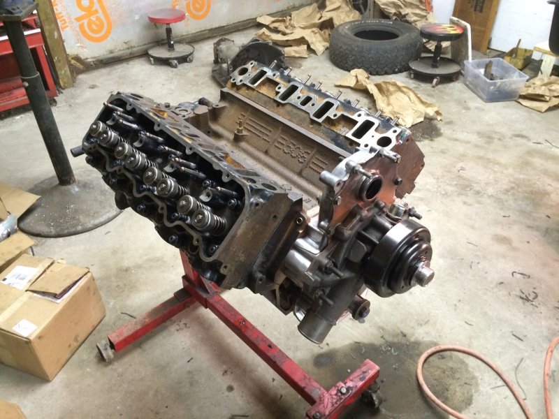
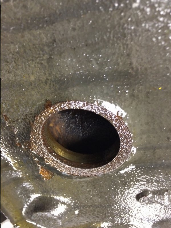
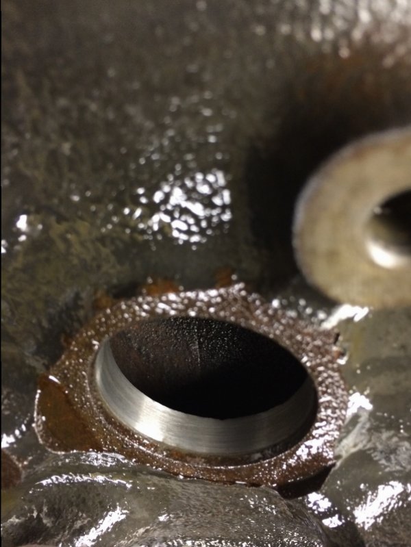
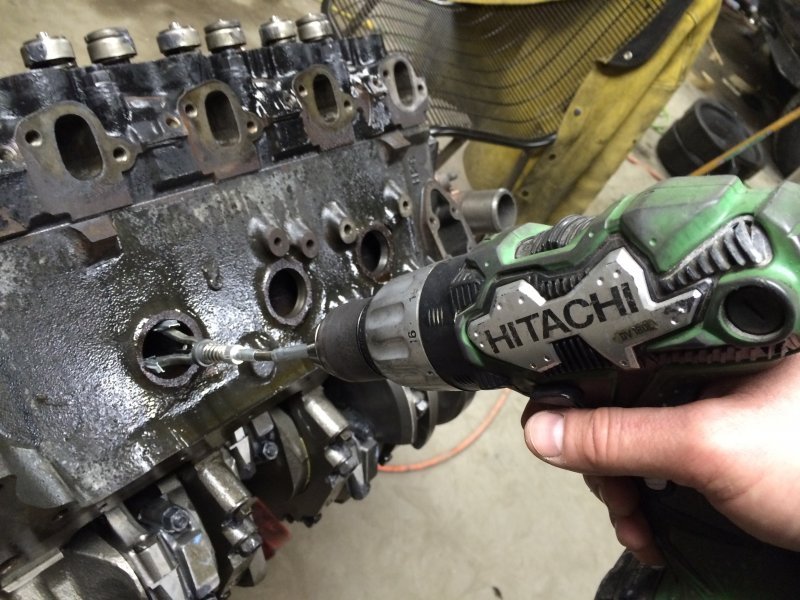
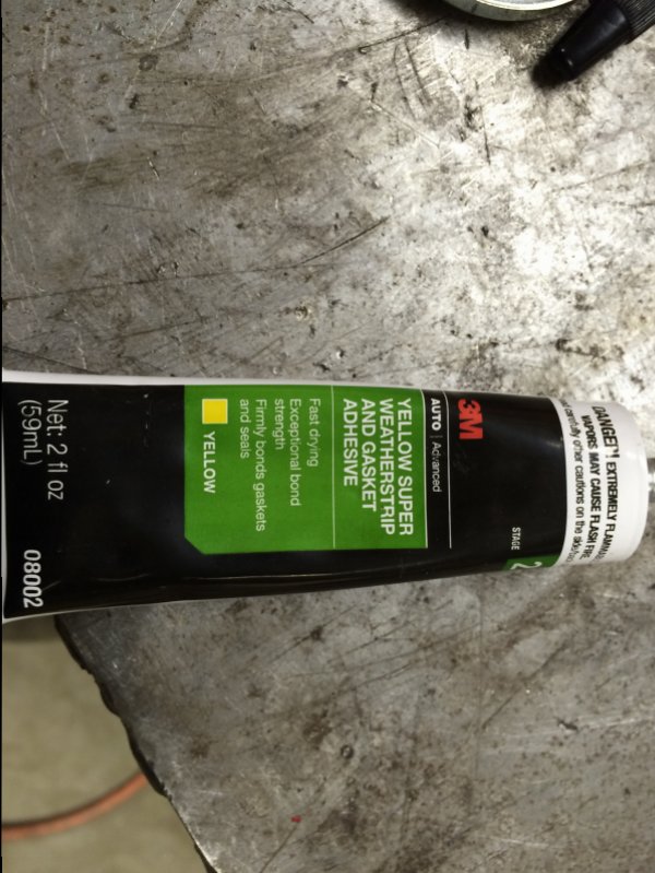
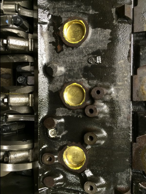
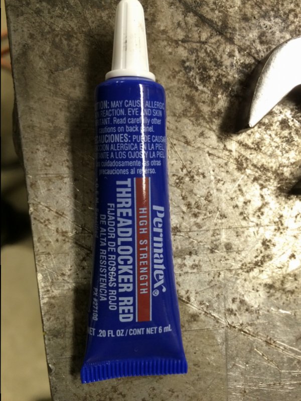
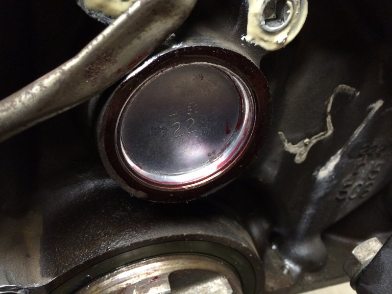
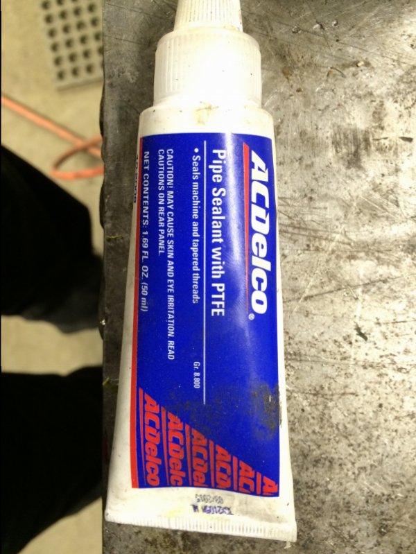
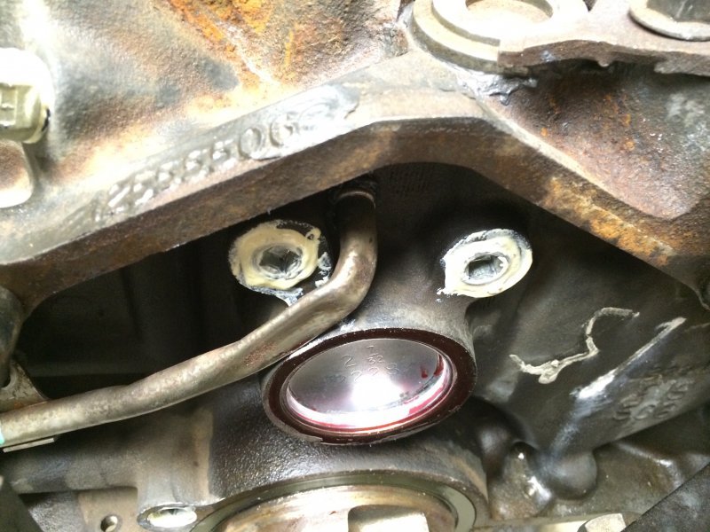
A little more progress tonight. I got all my freeze plugs in finally. Per Fermanator I used 3M yellow weatherstrip adhesive on the soft plugs in the cooling jacket and the GM thread sealant on threaded plugs. I also used a brake hone on the hole in the block to get the rust off the metal before I cleaned the surface. Per Will L I used Red Threadlocker on the rear cam plug. Tomorrow Is mostly masking and then it gets paint finally. Can't wait to see it with color finally!! I haven't received my parts from Harland Sharp yet so I won't be able to do final engine assembly and installation this weekend, so I'll start working on fuel system stuff. I'm hoping to have her most or all together later next week but we'll see how efficient I am with time and when I get the parts from HS.
image.jpg image.jpg image.jpg image.jpg image.jpg image.jpg image.jpg image.jpg image.jpg
 
Thanks for the info. Yeah I thought it was a matter of the way they were rating it, but thank you for inspecting further. Yep, we'll see if Heath is giving me as much fuel as I need....if not I'm already planning WMI for cooling but also for a little additional fuel. And if that doesn't do it maybe a little propane too??? We'll see. Not too many places to hide reservoirs in the Tahoe.
Perhaps tucked up under between rocker and chassis at drivers side rear 1/4 panel.
 
Back
Top