• Welcome to The Truck Stop! We see you haven't REGISTERED yet.

    Your truck knowledge is missing!
    • Registration is FREE , all we need is your birthday and email. (We don't share ANY data with ANYONE)
    • We have tons of knowledge here for your diesel truck!
    • Post your own topics and reply to existing threads to help others out!
    • NO ADS! The site is fully functional and ad free!
    CLICK HERE TO REGISTER!

    Problems registering? Click here to contact us!

    Already registered, but need a PASSWORD RESET? CLICK HERE TO RESET YOUR PASSWORD!

'95 Engine build

I guess that's why taking pictures of everything before/during disassembly is so important to an efficient reassembly - knowing what goes where and how - especially if it's several months/year(s) between coming out and going back in.
Agreed. I wasn't the only one taking things apart, though. Some was done in my absence. The things I took off were mostly photographed and hardware put into labeled bags. Other parts just got taken off, cleaned and ended up in the bed of my truck for me to guess where they go at a future date.
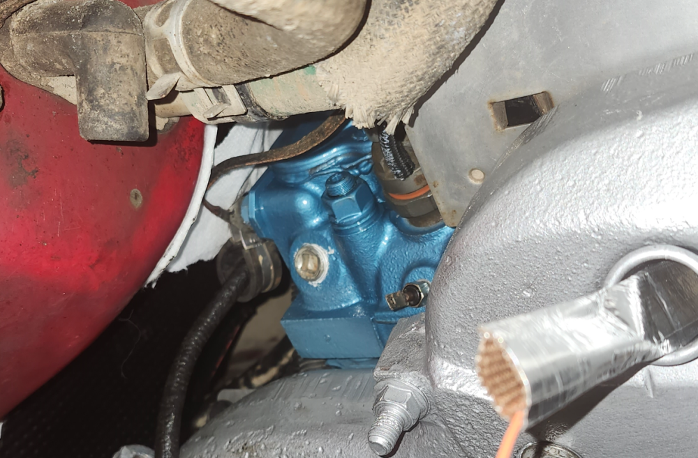
The battery to starter cable is clamped there.
I was wondering about that after looking at it again today. Thank you.

Any ideas on where this clamp mounts to hold the transmission line?
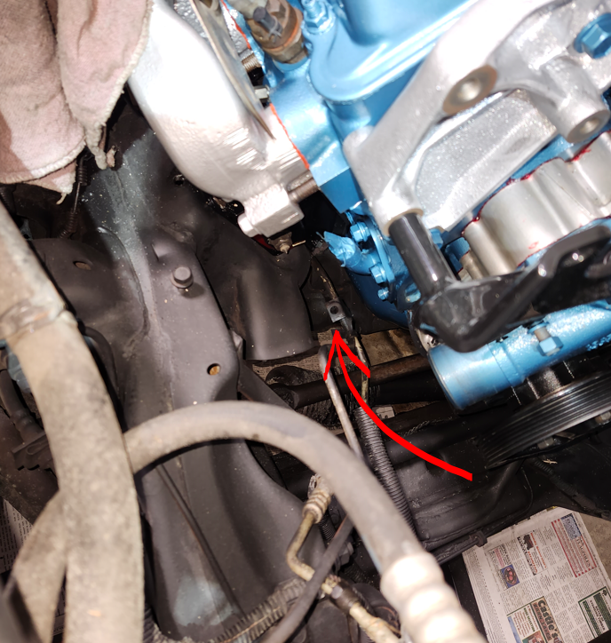
1703985523789.png
 
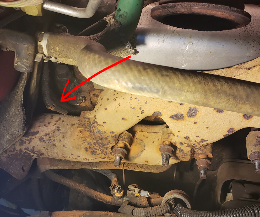
I mounted a clamp on the back of the head to hold the glow plug wire up off the exhaust manifold. I don't remember how it was routed originally either but it wasn't long enough to route with the others in between the heat shield and the block at the starter.
1703985732249.png
It came from the top somewhere, but I'm not sure where.
1703986204616.png
 
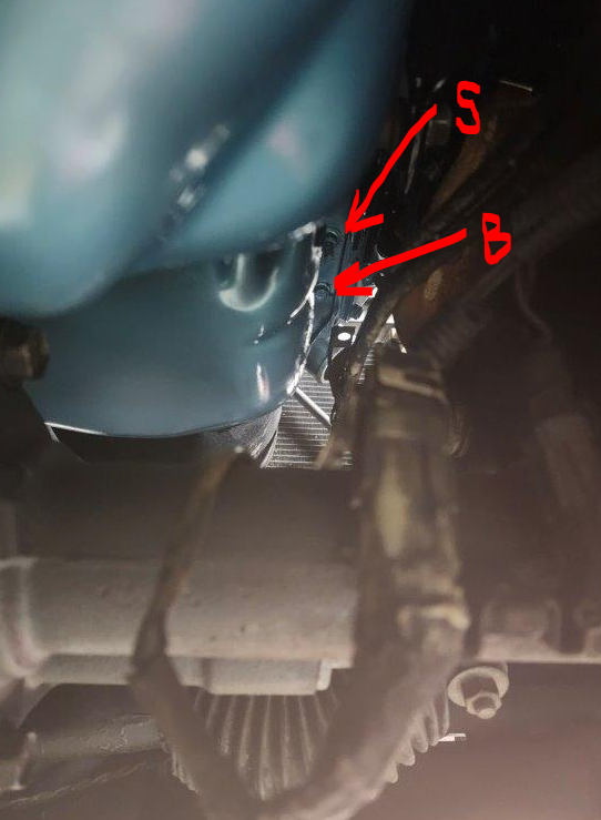
The stud goes in the first hole.
The bracket goes on the 2nd hole with a bolt.
That is how GM did it. I'm sure there must have been a purpose
for the stud but I have not seen it.
You will notice the bracket fits snug in the pan rail.
That keeps it from twisting when you tighten the bolt.
 
Ok, so I'll need to switch the bolt and stud I have labeled, then?

There are studs on the driver side as well. I was thinking those would hold an oil line bracket but I can't find one. I do have the one that goes on the small bracket that bolts to the motor mount, however. It looks like it holds both lines using the plastic retainer.
 

Just tying these together.

Transmission line bracket secured as mentioned above too, just as a follow-up

At some point the bell housing bolts were mentioned whether on this thread or another. Just as an FYI for someone looking to tackle the project, I got to the top bell housing bolts with relative ease from the top. There's plenty of clearance in front of the firewall that I was able to use a speed-wrench to get the studs tightened up. In fact, I kept neglecting to secure the right clamps to the stud on the driver side so I ended up doing it three times - all from above. If that big harness wasn't in the way, it would have been a real cake walk.
 
Last edited:

Just tying these together.

Transmission line bracket secured as mentioned above too, just as a follow-up

At some point the bell housing bolts were mentioned whether on this thread or another. Just as an FYI for someone looking to tackle the project, I got to the top bell housing bolts with relative ease from the top. There's plenty of clearance in front of the firewall that I was able to use a speed-wrench to get the studs tightened up. In fact, I kept neglecting to secure the right clamps to the stud on the driver side so I ended up doing it three times - all from above. If that big harness wasn't in the way, it would have been a real cake walk.
I forget the torque on the bell housing studs.
Always torqued the nut a little lighter. So the stud didn't want to spin with the nut.
I had that on more than one occasion.

The nuts don't do much. As long as the stay snug, they're good
 
Sometimes it's the littlest things that take the most time.

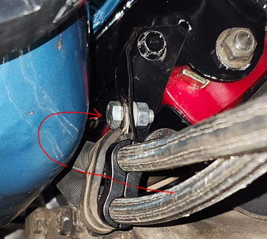
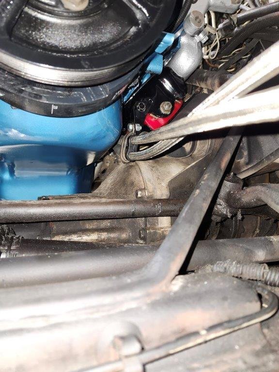
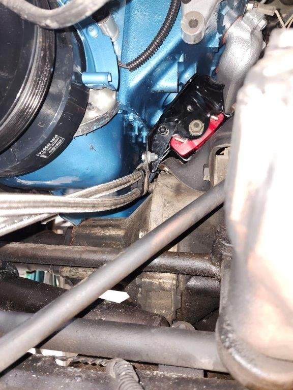
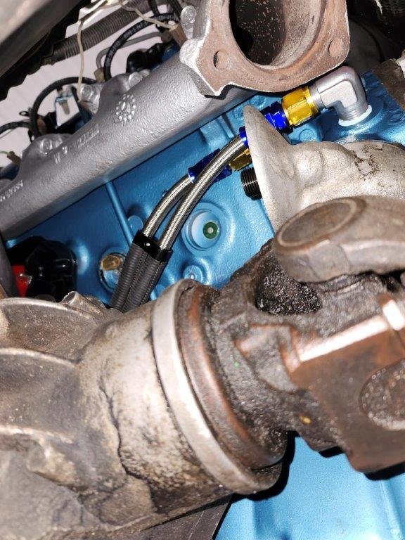
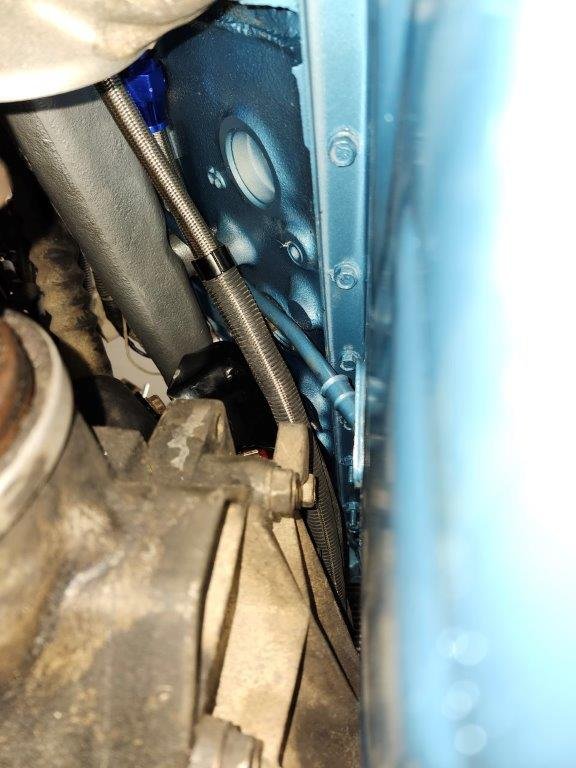
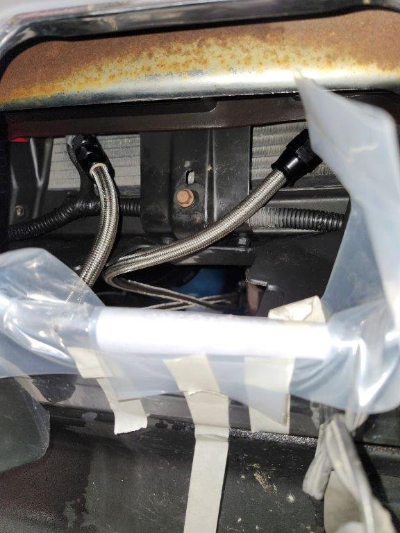
Oil lines made and installed. They are 1/2" SS braided PTFE good up to 400 degrees F. The lines were on a week or two ago but I was waiting on clamps. First set I got was too big for the OD on the braided lines so I had to order replacements. I had to change plans since I had originally planned to use the twin aluminum clamp on the factory bracket. I had it positioned up here but the lines were rubbing on the motor mount and dipstick tube. Centerline for the clamp was bolted where the arrow points.
1707697922504.png
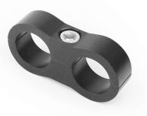
After a couple hours trying different things, I decided I would make a bracket to fasten in the same place the original bracket was. Then I realized I might be able to use the factory bracket and drop below with a clamp I had on hand. After test fitting the setup, I formed my clamp with a twin bolt setup to match the oil lines and fastened it all down. Now the oil lines don't rub on anything. I added convoluted tubing just in case they become "lazy" and start leaning toward something where they're not welcome.
20240211_175932.jpg20240211_175940.jpg20240211_175952.jpg20240211_180006.jpg
 
Through the front, the lines are as shown. Two 45 degree fittings out of the bottom of the cooler. One is slightly angled toward the front (the one on the left) and the other is in line with the cooler. I have a couple more twin clamps to add to them to get them routed neatly.
20240211_180033.jpg
These are the twin clamps I'm using.
1707698599793.png
 
I am just about finished up with the oil lines. I added two more clamps and some edge guard since one of the lines touches the bracket which holds the oil cooler. I'll cover the braided lines with black convoluted tube when I'm done so they're not as visible through the hole in the bumper. I've made a little progress in that I got the power steering pump mounted, as well as the alternator. Apparently there's a bolt that fastens to the block from the PS bracket that isn't so obvious from above. I had a bolt for it, though and was able to get it secured.
20240217_182959.jpg
 
I ended up using the aluminum tube for the heater hose. I ordered a molded hose for the one coming right out of the heater core. It had two 90 degree bends in it and then I used a short 5/8" section up at the water neck. I did have to form it in order to pull it back from the hose barb in the crossover. I didn't want the metals touching underneath the hose. I used a V-belt pulley as my form and made my bends with that so as to not kink the tube. The forming split the plastic cover, so I'll hide that with something too. No damage to the metal though.

I set the radiator in tonight and got the transmission lines hooked up along with the lower hose.

I did insulate the hose coming out of the firewall. I've also insulated the two heater hoses that run beside the turbo. From the factory, it looks like only the one on top was insulated but I covered them both.
20240217_182934.jpg20240217_182940.jpg20240217_182946.jpg
 
Is there another method anyone uses to install the fan clutch or is a spanner wrench the weapon of choice? I'll be using the spin on type from now on.
20240217_183014.jpg
 
I use this one but there is some modification necessary to make it work. you have to grind some on the inside near the pegs so it will sit down into the holes on the pump pulley.

 
As an Amazon Associate we earn from qualifying purchases.
Please excuse the amazon associate quote, not sure why that pops up when I share a link. I'm not affiliated in any way with amazon! I think they changed something on their site that does this.
 
It turns out we already had the wrench to fit the nut on the clutch - it was a MAC tool that hadn't ever been out of the bag. I put it on the nut and tapped it lightly with a rubber mallet while I held the water pump pulley with my hand. Is that about right or do I need to get serious torque on it?

I'm starting to run low on loose parts.

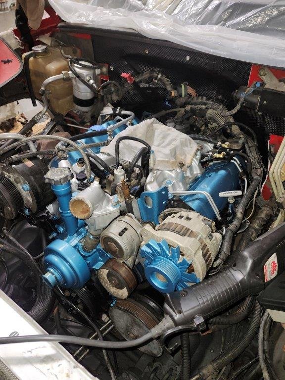
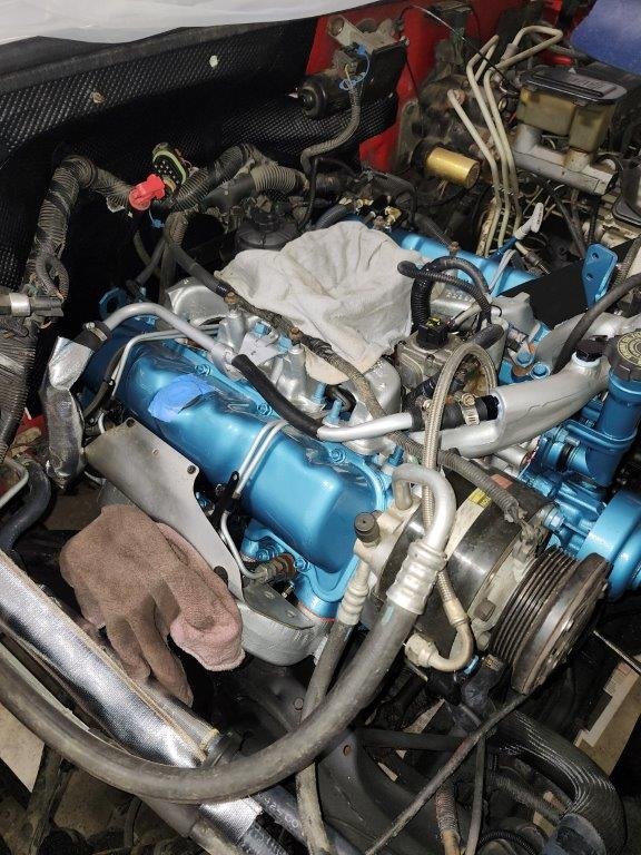
The turbo is left to do. My plan is to put on the old one then get this started up, get the timing correct, then take it back apart to put on a new turbo and intercooler. If anything looks out of order, please speak up. It has gone slow enough that I hope I've got things taken care of up to this point. As far as I know I have the turbo and upper intake to install as well as the tube for the boost. This doesn't include the inner fender and heater hose from the overflow tank to the T in the lower radiator hose.
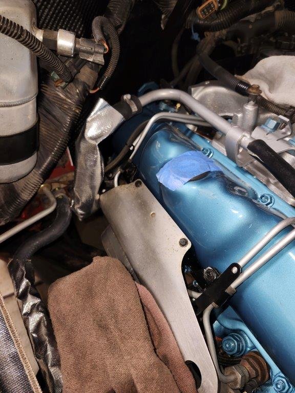
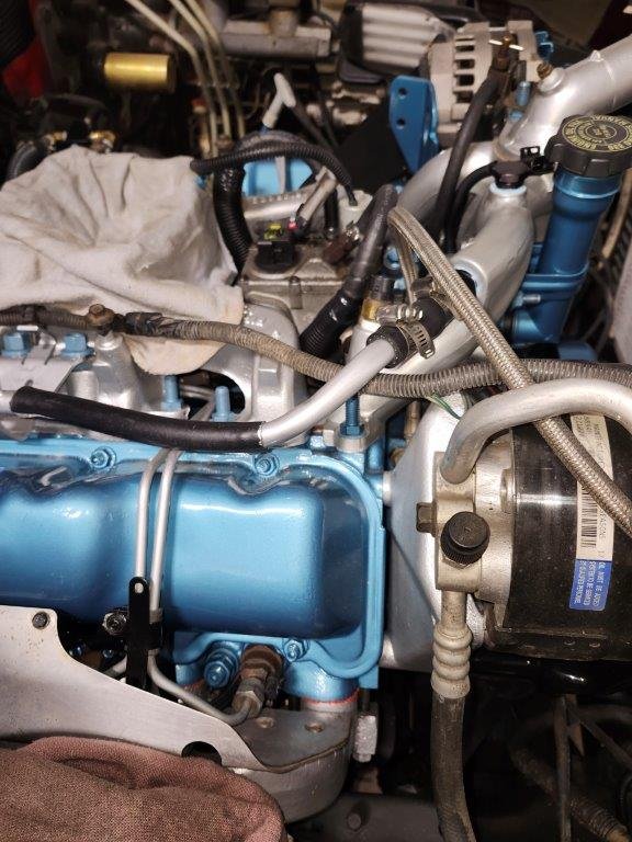
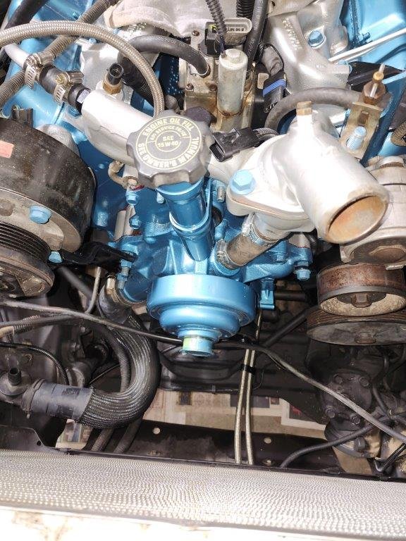
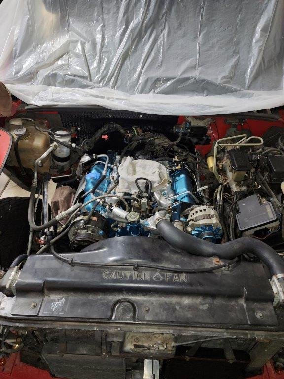
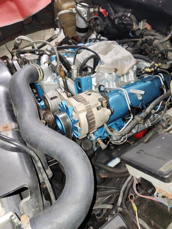
20240218_175444.jpg
20240218_175456.jpg
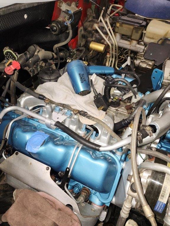
20240218_175845.jpg
 
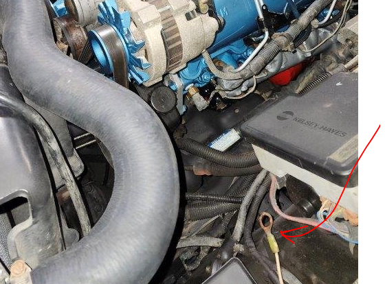
looks like a loose ground wire by the abs motors and not sure what that large connector up near the fire wall is but most important is your other half will be looking for her hair dryer LOL

all aside it's lookin good!
 
This one here? If so, it hooks to the battery. Batteries not in yet but thank you for pointing it out.
1708304046013.png
Connector up by the firewall is for the injection pump harness which I also failed to mention that is yet to be installed. Coming up also.

I have a big fat ground or two that came on the engine that I plan to find a home for as well.

Ha! I had a Dayco sticker to take off a radiator hose so I needed the dryer. Actually, it's what we have in the shop for a heat gun. It works well and isn't as aggressive as a regular heat gun. I found it ironic that it is pretty darn close to Olds Blue Metallic so I laid it in the intake and took the last photo.
 
Back
Top