We don't need to see the backing plate, we need to see the pump impeller, that's where the flow originates...
Navigation
Install the app
How to install the app on iOS
Follow along with the video below to see how to install our site as a web app on your home screen.
Note: This feature may not be available in some browsers.
More options
-
Welcome to The Truck Stop! We see you haven't REGISTERED yet.
Your truck knowledge is missing!
- Registration is FREE , all we need is your birthday and email. (We don't share ANY data with ANYONE)
- We have tons of knowledge here for your diesel truck!
- Post your own topics and reply to existing threads to help others out!
- NO ADS! The site is fully functional and ad free!
Problems registering? Click here to contact us!
Already registered, but need a PASSWORD RESET? CLICK HERE TO RESET YOUR PASSWORD!
You are using an out of date browser. It may not display this or other websites correctly.
You should upgrade or use an alternative browser.
You should upgrade or use an alternative browser.
Sucked Near A Quart of Oil, Temp went to 210.
- Thread starter MrMarty51
- Start date
MrMarty51
Well-Known Member
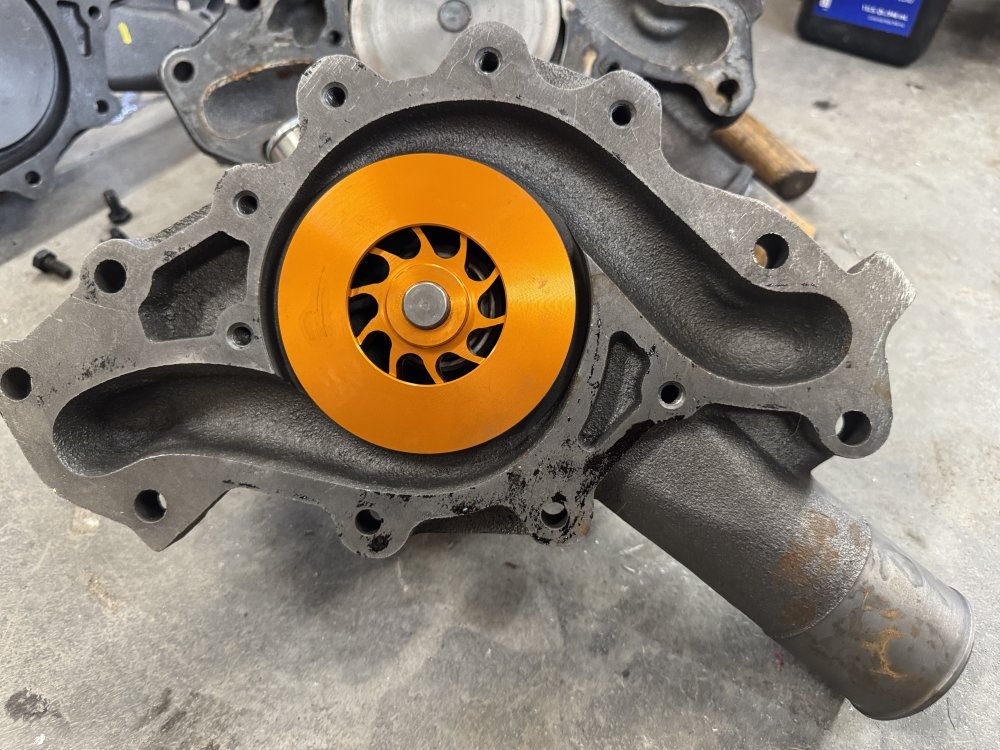
I thought the blockage of the pump to the backing plate would affect the flow.We don't need to see the backing plate, we need to see the pump impeller, that's where the flow originates...
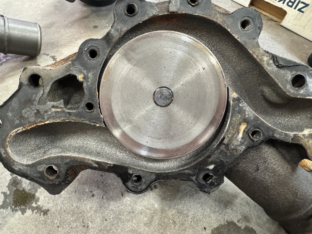
The old NAPA pump.
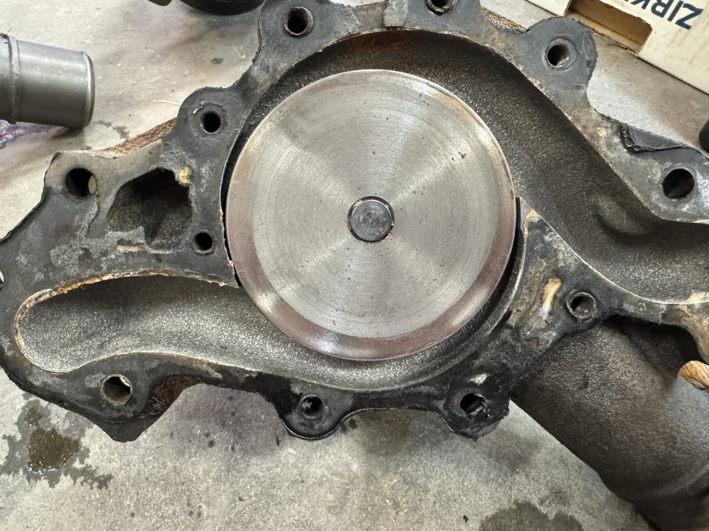
It appears it had been slightly dragging on the backing plate but the BP does not show scuffing.
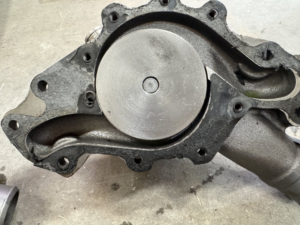
CKO.
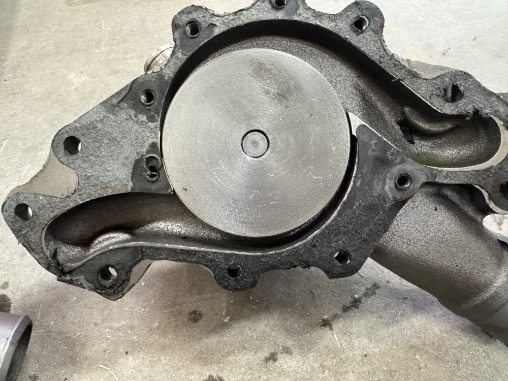
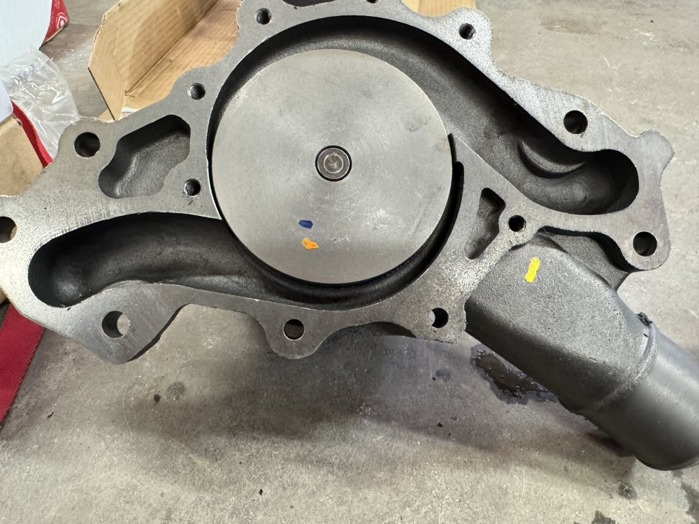
New AC Delco.
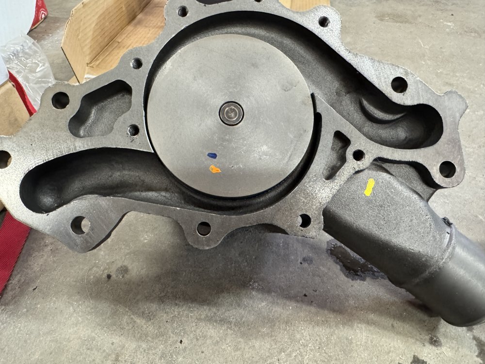
MrMarty51
Well-Known Member
Will L.
Well-Known Member
That orange one is the “flow kooler” brand. I caught them in lie about the volume it flows. Leroy accepted it was doing the volume the manufacturer says it does, like all their victims. Last I heard from that outfit they were going to go back to testing to get the volume up and verify it putting out balanced volumes- but they never got back to me and when I contacted them about a year later- the new guy knew nothing about the guy I spoke to who quit and the company wasn’t doing any testing…
MrMarty51
Well-Known Member
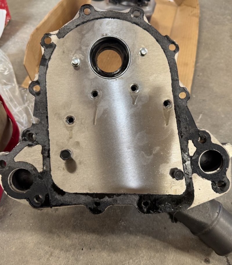
What do You think about doing some die grinding on the new AC Delco coolant pump so that the backing plate and the channels in the pump align a little better ?That orange one is the “flow kooler” brand. I caught them in lie about the volume it flows. Leroy accepted it was doing the volume the manufacturer says it does, like all their victims. Last I heard from that outfit they were going to go back to testing to get the volume up and verify it putting out balanced volumes- but they never got back to me and when I contacted them about a year later- the new guy knew nothing about the guy I spoke to who quit and the company wasn’t doing any testing…
Kind of like grinding heads to intake manifold ports for a more undisturbed flow.
Would that help on the flow from the pump to the block ?
Its not much of a misalignment but it might have a slight affect on the flow.
Big T
Well-Known Member
Not sure what you’re getting at. It looks like flashing is present on the hole to the right and to the left the backing plate is misaligned. If that’s the case, I would grind the flashing off on the right and grind the plate on the left. Before I’d do any of that, I’d pull all the bolts to see if the plate will align with the water ports, then adjust/grind the bolt hole holes.What do You think about doing some die grinding on the new AC Delco coolant pump so that the backing plate and the channels in the pump align a little better ?
Kind of like grinding heads to intake manifold ports for a more undisturbed flow.
Would that help on the flow from the pump to the block ?
Its not much of a misalignment but it might have a slight affect on the flow.
View attachment 93966
Something is up for this alignment to be consistently wrong across a number of water pumps, especially when no one else has experienced it.
You can match that little bit and grind it if you want, if you line it up before tightening the bolts it won't be like that.
As for the w/p's, this is how to tell a higher flow vs a standard flow pump tight is high flow, a gap like the flowkooler is lower flow...
FYI, flowkooler now has one with a bigger impeller like the high flow others ....
I see nothing wrong with the pumps you posted....
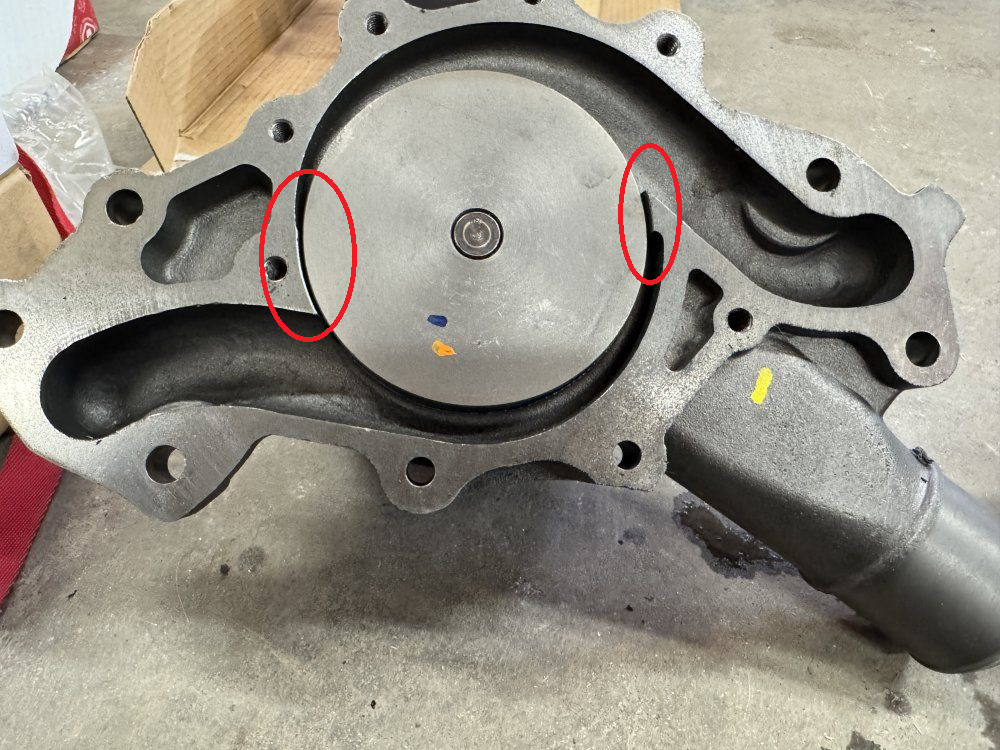
As for the w/p's, this is how to tell a higher flow vs a standard flow pump tight is high flow, a gap like the flowkooler is lower flow...
FYI, flowkooler now has one with a bigger impeller like the high flow others ....
I see nothing wrong with the pumps you posted....

Will L.
Well-Known Member
Big T has it right on start with alignment- it seems to me your backing plate isn’t quite right. Mass production has errors. And ANYTHING CAST that has flashing- always remove it.
Anything that helps flow to the passenger side is ok. But remember, just like people trying to port heads make errors: bigger is not always better. “Gasket match” yes. But look how the holes line up on the block to the plate. Then plate to pump. If you make pump& plate match but they aren’t aligned with block entrances, it doesn’t matter.
And yes Chris is on point to hi flow vs low flow and the gap at the wheel.
Afaik flow kooler never fixed their issues, and were in-fact having worst fitment issues of all. So imo just skip them.
On the different Delco pumps- look at the pic you posted and Chris posted. Two different pumps and one has a restriction in flow to the driver side, the other doesn’t. Idk if this is error in casting or something that affected one being balanced and the other not. Could be something to id, might be ignored. Imo run ONLY the one identifed as balanced by the part number. We know Bill was selling it and some believe he was “pushing it” but he could have “pushed” any of them.
And that number was the one identified by the GM Engineer.
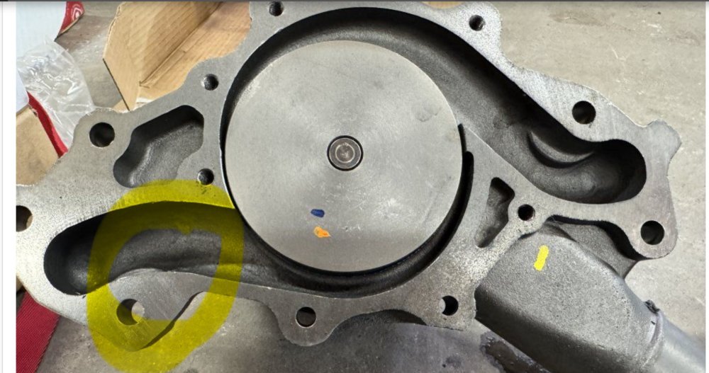
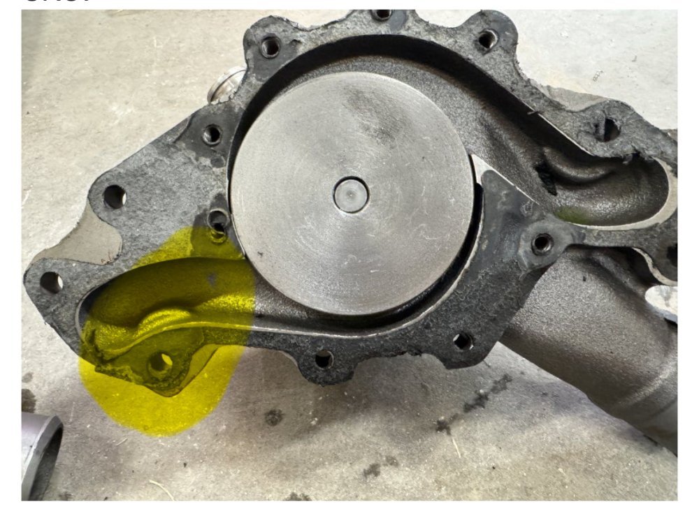


Last edited:
MrMarty51
Well-Known Member
The weird thing is the old original backing plate fits all the pumps exactly as the Quad Star backing plate.
MrMarty51
Well-Known Member
Big T
Well-Known Member
These were all tested on the 6.5 Optimizer? If so, I would stick with the new AC Delco. I also commend your efforts to swap these in and out so quickly.Engine was cooling real nice with this pump.
View attachment 93974
Engine was not cooling good with this pump.
Temperature gauge before I got home was running on the 220 peg.
View attachment 93975
This AC Delco pump is closer to the pump that was cooling good.
I think.
View attachment 93976
On the bad Chinesium, the pump vane does not look like it’s attached solidly to the shaft. Could it be spinning on the shaft while under load?
MrMarty51
Well-Known Member
Thank You @Big TThese were all tested on the 6.5 Optimizer? If so, I would stick with the new AC Delco. I also commend your efforts to swap these in and out so quickly.
On the bad Chinesium, the pump vane does not look like it’s attached solidly to the shaft. Could it be spinning on the shaft while under load?
I have to have this truck road worthy dependable before the 18th of June. Its going on a long journey on that day. To West Salem Ohio, south of Cincinnati, then drift around Ohio for a while. Be back to Miles City the 29th of June. Then straight way off to the cabin, another 320 mile round trip journey.
I’ll have to take a feel of the impeller to shaft next time I get to the garage.
The Quadstar backing plate matches perfectly to the timing chain chest housing.
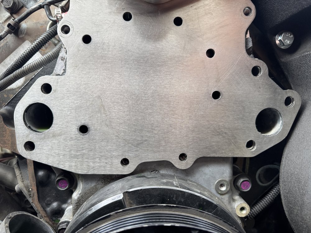
I did do some die grinding and matched the openings of the plate to the pump.
While the cooling system is drained down, going to install two new 190* thermostats.
I had a choice of 190s from Oriellys or 190s from NAPA.
I chose NAPA.
This is the numbers on the box that the new coolant pump came in.
I’m not used to seeing these two part parts numbers. I’m more accustomed to seeing numbers more like the GM numbers.
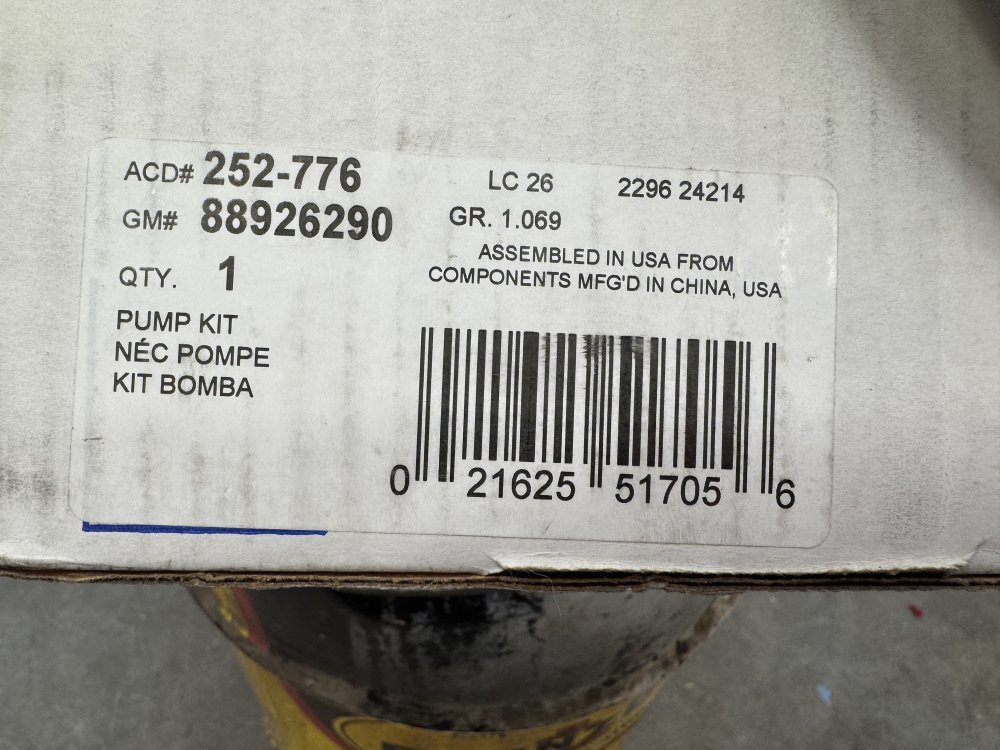
JayTheCPA
Well-Known Member
MrMarty51
Well-Known Member
Will L.
Well-Known Member
That’s a good way to get all the life from a tire right there!
MrMarty51
Well-Known Member
I was thinking that.That’s a good way to get all the life from a tire right there!
Good thing its wet pavement of else that tire would get mighty tired.
Also, he might not have enough torque to break them loose like that, and, if He did, bound to be a rollover for sure.
MrMarty51
Well-Known Member
Thinking I need to build a big funnel, dump a five gallon bucket of water through the radiator and make sure there is no obstructions within.
No radiator shops here anymore that could do the full flow test on the radiator like back in the old days.
No radiator shops here anymore that could do the full flow test on the radiator like back in the old days.
MrMarty51
Well-Known Member
The book says nothing about using a sealer on the waterpump bolts.
There is coolant within the main waterpump bolt holes into the block.
My past experiences with such conditions is coolant leaking past th threads of the bolts.
Is there any recommendations from the group to use or to not use sealer on the bolt threads ?
There is coolant within the main waterpump bolt holes into the block.
My past experiences with such conditions is coolant leaking past th threads of the bolts.
Is there any recommendations from the group to use or to not use sealer on the bolt threads ?
dbrannon79
I'm getting there!
on the pics you posted I could not tell where you ground out on the pump to match the ports of the backing plate. can you post were you ground into?
on that one that you said wasn't cooling well it kinda looks like the impeller is slightly out on the shaft where the others look like the shaft is protruding out slightly further than the impeller. if there is a larger gap under the impeller to the pump body, that might explain why it's not pushing as much coolant flow as the others. I would think it's not just the gap on the sides of the impeller but also the gap behind it to the body too.
My thinking is the only real way to test flow and balance would be to have someone mock up a pump and timing cover not attached to an engine but have it in such a way flow meters could be attached to each outlet of the pump where it meets the block and use a motor to drive the pump monitoring flow on each side. taking into account that some flow from the pump on the hose bib for the heater would come from one side or the other. I bet we have members here who could do such a thing, it would be interesting to see results of that.
Will L.
Well-Known Member
It is not just the pump… how the heater hoses tie in affect it also. This is why there is all the warnings about bypassing a bad heater not just blocking the lines and why in Hummers they have to reroute one hose down into the lower hose.on the pics you posted I could not tell where you ground out on the pump to match the ports of the backing plate. can you post were you ground into?
on that one that you said wasn't cooling well it kinda looks like the impeller is slightly out on the shaft where the others look like the shaft is protruding out slightly further than the impeller. if there is a larger gap under the impeller to the pump body, that might explain why it's not pushing as much coolant flow as the others. I would think it's not just the gap on the sides of the impeller but also the gap behind it to the body too.
My thinking is the only real way to test flow and balance would be to have someone mock up a pump and timing cover not attached to an engine but have it in such a way flow meters could be attached to each outlet of the pump where it meets the block and use a motor to drive the pump monitoring flow on each side. taking into account that some flow from the pump on the hose bib for the heater would come from one side or the other. I bet we have members here who could do such a thing, it would be interesting to see results of that.
This is a big part of why I was talking about two separate thermostats that can open up one for left side and the other for right side like most large semi engines do. I was even entertaining the idea of doing split radiators like they do where it is two completely different cooling systems- we did that testing back in the 90’s but the problem came in on ds4 systems getting one half of the engine under 160 and the other over - and the ecm not able to run them the same. The plan was to have two sensors report to an intermediary, and send the coldest in for low temps and send the highest in for high temp. It was the next day when we learned of the imbalance…
But on a db2 truck like mine it wouldn’t matter- anything to cold advances timing and anything too hot just sends the gauge up. No computer control to do anything.
If a person wants to experiment with their truck, then yes just ha e the whole system together, except make two hoses to remotely mount the crossover and have two flow gauges between head and crossover inlet.

