• Welcome to The Truck Stop! We see you haven't REGISTERED yet.

    Your truck knowledge is missing!
    • Registration is FREE , all we need is your birthday and email. (We don't share ANY data with ANYONE)
    • We have tons of knowledge here for your diesel truck!
    • Post your own topics and reply to existing threads to help others out!
    • NO ADS! The site is fully functional and ad free!
    CLICK HERE TO REGISTER!

    Problems registering? Click here to contact us!

    Already registered, but need a PASSWORD RESET? CLICK HERE TO RESET YOUR PASSWORD!

VSS problem

Goose57

Well-Known Member
Messages
275
Reaction score
699
Location
Eureka Mo.
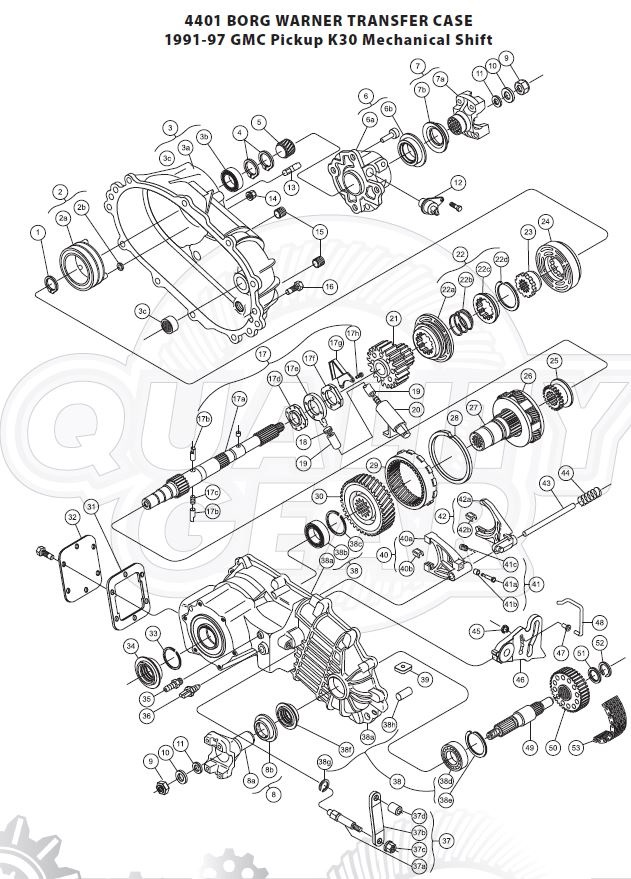
hi all I didn’t see a section for transfer cases. I pulled the output sensor out of the rear of my BW4401 transfer case broke off the hold down bolt. Could not get to it so I removed the 6 mounting bolts and rotated the case down to where I could get to it and repair it. Rotated case back up installed case bolts and now the
1370 640 001 - SPEED SENSOR, BORG WARNER 4401/4470/4472 TRANSFER CASE ***NEW*** - Picture 1 of 4


sensor won’t go back in. It’s bottoming out on the sensor wheel. It’s like the same sensor grew an inch. Am I missing something. The sensor wheel is on the main shaft and spins when I rotate the drive shaft. I can’t see the sensor wheel moving out of place. Is the wheel supposed to be located directly below the sensor or am I crazy. I’m going to try a bore scope to see if I see anything. I hope I don’t have to pull the case. Thanks
 
I know it's a dumb question, but check the depth of the old sensor compared to the new one. the parts house could have given you an incorrect sensor or was possibly boxed wrong.
 
My only guess would be if when you rotated the case it might have separated some and things inside are out of alignment. I would need to see a visual of the transfer case and what section you un-bolted and rotated to know more. maybe get an inspection mirror so you can see up in the hole. place the trans in neutral, jack up the wheels so you can turn the drive shaft while looking in the hole making sure the reluctor wheel is in the right spot.

I'm sure others with better knowlage on this t-case will chime in soon.
 
I am wondering if the gear or reluctor in the t-case is made of plastic. looked online for a diagram to get a mental picture on how you rotated the housing to access the bolt. I would wonder if when you extracted the broken bolt maybe something got jarred loose or out of place in that area.

1732684767981.png
 
Thanks guys, here is a step by step that might help.
Broke sensor hold down bolt. Removed sensor
Removed trans. cross member lowered trans. driveshaft still in.
Removed six bolts that hold the case to the auto. trans. adapter.
Trans. in neutral, transfer case not sure, had to take the linkage off to get to the six case bolts.
Rotated case 30-35 deg. Repaired bolt.
Rotated case back up installed six mounting bolts
Original sensor wouldn’t go back in. Could still see the o-ring on the sensor.
I did rotate the drive shaft a couple of times to check if the speedo gear spins.
Yes I’m with you on an alignment issue because of the different angles of the case and drive shaft when I lowered the trans. Also rotating the drive shaft with the case in gear.
Boy that’s a lot of slop on the main transfer case shaft. but the sensor might be that close to the speedo wheel.
I’m going to raise the trans. to original position and see if the sensor goes back in if not spin the wheels w/case in gear to see if the sensor wheel goes back in place.
Will, the sensor goes in up to the o-ring. It just lacks a little bit from being in. I think we may of figured it out by just writing this post and of course your guys input😎 I’ll keep you posted. Thanks.
 
I too think the o-ring might be your issue from getting it in. it's giving you some resistance. try this to verify.... get you a measuring device (small metal ruler is best) pocket screwdriver or something, stick it into the hole and note the depth. then measure the same on the sensor and see where you end up. by doing this will tell you if applying some force on pushing the sensor into the hole will make it contact the gear inside.

Yes the sensor will "almost" touch the gear. it has to be close enough to pickup the movement of the gear, there will be a very tiny air gap between the gear and the sensor probably less than a 1/16 of an inch. then you can slather some lube on the o-ring and push it in without worry of breaking anything. it might take some pushing and twisting action to get it into place.
 
Thanks guys, yes I wondered about the o- ring. Believe it or not it’s still pliable greased it and lightly tapped on it. Yes I did a depth measurement it’s about 5 or 6mm from going in. I do believe the shaft w/ the wheel on it is raised up from lowering the trans. w/ the drive shaft still in it. If that is the case I might have to replace the bearing or bushing on the shaft in front of the wheel. Just more work while waiting on
the defective IP decision. Soon as I get back out there I will let you guys know.
 
My suggestion was gonna be what our Alaskan buddy said. Remove oring to test fit.

You should almost always use the liquid the oring is sealing to lubricate it.
I say almost because one time and one time only I saw a warning not to on a small aircraft engine that had orings on the fuel system and it said use motor oil not fuel.
 
Hi all got the sensor back in. Took the o-ring off like you guys said and it went all the way in. New o -ring fixed!! I was way overthinking it. Thanks for all the help.
I know it is said, and recommended to lube seals with the same product that they will be bathed in when the unit is back together.
I pretty much follow that rule until it comes to O-Rings.
No matter what type of fluid they might be holding back, I use dielectric grease on O-Rings.
Allows them the slide into their bores with little to no resistance and the dielectric grease, so far, has never damaged components from that grease.
 
Hi all finally got the repaired IP back from Quadstar installed and running. They informed me the rotor was install backwards. Repaired it and resealed it and bench tested it.


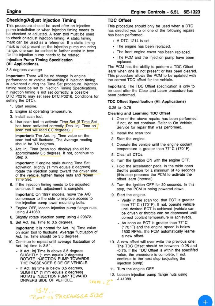
I have the timing set at 3.5 and TDC Offset at -114. I tried a couple of times to get the Offset between-0.25 and 0.75 but couldn’t because it changed the timing setting above 3.5. i also did the Cleared and Learning TDC Offset using a 1997 timing procedure someone on here sent me and said it would be OK to use it on my 95’ OBD1 w/ my Tech2 .
1737994196877.jpeg
Here is another procedure I found should I use this one. This one is entirely different.
I’ll post some scan tool data and get back to you guys. Probably w/more questions😎 I’m have some more questions on CDR outlet hose routings. But I’ll start a new thread this one is getting crowded w/ to many different subjects. Thanks guys.


OBD1 timing procedures for oem factory tune* - results may vary with aftermarket tunes
- Bill Heath's tunes respond normally with scantools (courtesy of member Turbovanman)

All DTC's must be cleared prior to performing Timing and TDCO procedures

To clear your OBD1 DTC's, put a wire jumper into pins A/B in the DLC connector under the dash, turn on the key, push brake and APP to the floor and hold for 1 minute or so. Turn off key, release pedals, then turn on key again. Should have cleared all codes, you should get a flashing 12. (courtesy of member JiFaire)

I compared procedures using a new TECH2 and GMTDScan Tech to find no difference, except that I prefer GMTDScan Tech as more user-friendly

Standard procedure

When installing a replacement DS4**, or resetting timing, start with the Engine Shut Off solenoid in 90* vertical to horizontal plane across valve-covers - this should within a RCH of +3.5* Base timing

Start the engine, do an initial scan on engine parameters for 180*F ECT, idle speed 695~750rpm, ACTUAL IP timing +8.5*BTDC, DESIRED IP timing +8.5*BTDC, TDCO -0.5*

ECT must be at operating temperature ~180*F or timing procedures are invalid - I prefer 195*F

Scribe a line across the IP and timing cover flange

Scribe a second line across the timing cover flange, 2mm to the right of the first line - 1mm = 2.5*

Loosen the 3 12pt nuts on the IP flange, rotate the IP, aligning the IP flange line to the 2mm line for a +5* advance, secure the nuts

Start the engine, scan again verifying at least +180*F ECT, ACT\DES +8.5*, idle 695-750rpm

Command TIMESET, rpm will increase, engine will hesitate and stumble as PCM determines new IP position, wait ~5 seconds, exit TIMESET

Command TDCO LEARN, engine rpm will again increase, and hesitate\stumble, will self-exit when new value is learned

Scan again for +8.5*BTDC ACT\DES IP timing, TDCO at -1.5*

NOTE: engine stumble\hesitation is resulted during the period when PCM wratchets OS timing 22* between minimum and maximum limits to determine IP position

----------------------------------------------------------------------------------

If initial scanned TDCO value is elevated to some level greater than -0.5*, this may indicate BASE timing is not +3.5*BTDC

In this case Command TIMESET, exit; command TDCO LEARN, rescan TDCO - if same value, you will have to punt: either

- move IP to exacty vertical and do the standard setup

- or move IP 1mm to right, do TIMESET and TDCO LEARN, scan for new value
repeat at smaller increments until desired TDCO value is attained - PCM will DTC for TDCO over-range at some value greater than -2.02* for OBD1

*Again, aftermarket tunes seldom comply, but TDCO values at idle always represent Base timing, if you interpolate after the initial scan:

-0.5* = +3.5*

-1.5* = +8.5*

----------------------------------------------------------------------------------------

** Alternately, having scribed the line across the IP\timing cover, remove the old IP, accurately measure the position of the scribed line to either end of the upper slot - transfer that dimension to the replacement IP, scribe a line, match that line to the timing cover line when installing the IP, and you should be within a RCH of the original timing, no timing procedures necessary - the IP machining tolerances are that close
 
sounds much better! having a -1.14 offset is what I would call close enough. it's not going to hurt anything. AK is correct on the 3.5 base timing. that is to get you in the ball park for optimal setting. the easiest way I have found to adjust it once your are close as in currently -1.14. leave the bottom two IP nuts semi-loose keeping the top one tight. use a good marker or paint pen and mark the IP to the timing cover where it's at so you have a reference point. then you can loosen the top nut (with engine off) and bump the IP a smigin one way or the other. then re-run the time set and relearn with the tech2 or GMTD. see were it lands. remember moving the IP the width of a strand of hair makes quite a bit of change.

This is where the hair pulling begins if you want it within GM factory spec. just be calm and patient. But honestly I would leave it where it's at being -1.14 and enjoy it. the only noticeable difference with it over max spec of -0.75 is slightly more rattle and maybe some extra giddyupness!
 
Back
Top