
Paveltolz
Доверяй, но проверяй
Projects Projects.
Taking a week off from work to get some space on the shelves.
Today I installed the Walbro pump and Wix filter I’ve had sitting on the shelf forever. I wanted to mount it all up so it wouldn’t hang below the frame. I made up a mounting bracket similar to Leroy’s (PMDCable.com) who sold me the pump and filter. I had to do it twice (of course) and it took most of the day.

I did mine opposite of his set up but fuel flows in the same order of Filter, LP, FFM….
Anyway, I filled the filter and the pump prior to sliding it up into place as I wasn’t if it needed priming or not. Started right up and kept running so that project is done. :thumbsup:
I also found the source of a mysterious knocking sound that I haven’t been able to figure out…downpipe and cross over are in contact. I’ll fix that little issue tomorrow.
Tomorrow: FTB, Fuel Filter Manager relocation and then…the Peninsular intake mod / ATT install.
During the road trip with Ted (635) and Paul (Sunshine) we ordered pieces parts to duplicate Ted’s intake. He runs a Peninsular upper through a couple of 90 degree bends to the Turbo. Yes, I know it actually flows the other way. At the Peninsular, the first 90 is part of a Cummins set up which opens up from 2.5” to match the 3” opening of the Peninsular. From the turbo he’s running a silicone hose with a molded 90 in it. That elbow is showing signs of softening up sooo
We decided that a 2.5” mandrel bent pipe would be better so let it be ordered, let it be delivered and I’m the guinea pig for this mod. Just know and understand that the set up will work with a GM-X or the ATT so long as there is enough play in the joints held together with 2.5 and 3 inch silicone couplers.
My one big concern was how to mount the ECM’s IAT and Boost sensors.:???: Ted’s lower intake was drilled and tapped during the build but I didn’t want the holes in case I decided to revert back to stock. That is where the idea for a “throttle body” spacer of sorts came up. A one inch spacer, milled to accept the sensors for the ECM and still have room so one could also tap gauge sensors as well as WMI stage 1 and 2, Propane Injection and whatever else.
The spacer’s 1” thickness is negligible as the Peninsular’s base is only 3/8” thick and the stock upper is over 1” which means you don’t even need longer bolts.
I’ve mocked up a wooden unit 1.5” thick (the IAT sensor is pretty thick and I kept splitting the 1” mockups. The final will be made from aluminum plate
A few pictures of how the wood mockup was made.
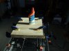
 Glue and press plywood together
 Trace using Peninsular upper and gasket as guides
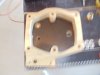
 Use old upper as drill guide in lieu of a drill press

 Drill holes for Boost and IAT sensors
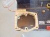
 I used a female NPT pipe fitting for IAT sensor. RTV was used to seal the fitting in place.
 Boost sensor in place (diagonal hole drilled from inside the spacer to the vertical to allow pressure to reach the sensor.
 In place and all holes line up and electrical connections will mate up as required.
 Peninsular upper with cummins elbow. Note the thickness at the bolt holes compared to the stock thickness in the "drill press" photo).
My neighbor has a machine to cut/mill the part and I’ve purchased enough aluminum plate to make a couple of mistakes. Unfortunately, he’s on vacation and I’m getting impatient as can be. So in the mean time, I picked up a scrap piece of aluminum plate large enough to work with and am having a roughed out unit cut. My jig saw just won’t do it (funny the success I’m having with this spacer in learning all the ways things just won’t work).:rolleyes5: The machinist is swamped so I may not get the piece back until next week. RATS. So, I’ve decided to use the wooden unit and have coated it with sanding sealer and engine paint so it won’t absorb outside moisture and inside oil mist from CDR as fast and am going to go for it. It will only have to last a few days and I want to play. :hihi:
Not sure how to get rid of the photos below, I thought I'd deleted them and they don't show up on edit.
Taking a week off from work to get some space on the shelves.
Today I installed the Walbro pump and Wix filter I’ve had sitting on the shelf forever. I wanted to mount it all up so it wouldn’t hang below the frame. I made up a mounting bracket similar to Leroy’s (PMDCable.com) who sold me the pump and filter. I had to do it twice (of course) and it took most of the day.
I did mine opposite of his set up but fuel flows in the same order of Filter, LP, FFM….
Anyway, I filled the filter and the pump prior to sliding it up into place as I wasn’t if it needed priming or not. Started right up and kept running so that project is done. :thumbsup:
I also found the source of a mysterious knocking sound that I haven’t been able to figure out…downpipe and cross over are in contact. I’ll fix that little issue tomorrow.
Tomorrow: FTB, Fuel Filter Manager relocation and then…the Peninsular intake mod / ATT install.
During the road trip with Ted (635) and Paul (Sunshine) we ordered pieces parts to duplicate Ted’s intake. He runs a Peninsular upper through a couple of 90 degree bends to the Turbo. Yes, I know it actually flows the other way. At the Peninsular, the first 90 is part of a Cummins set up which opens up from 2.5” to match the 3” opening of the Peninsular. From the turbo he’s running a silicone hose with a molded 90 in it. That elbow is showing signs of softening up sooo
We decided that a 2.5” mandrel bent pipe would be better so let it be ordered, let it be delivered and I’m the guinea pig for this mod. Just know and understand that the set up will work with a GM-X or the ATT so long as there is enough play in the joints held together with 2.5 and 3 inch silicone couplers.
My one big concern was how to mount the ECM’s IAT and Boost sensors.:???: Ted’s lower intake was drilled and tapped during the build but I didn’t want the holes in case I decided to revert back to stock. That is where the idea for a “throttle body” spacer of sorts came up. A one inch spacer, milled to accept the sensors for the ECM and still have room so one could also tap gauge sensors as well as WMI stage 1 and 2, Propane Injection and whatever else.
The spacer’s 1” thickness is negligible as the Peninsular’s base is only 3/8” thick and the stock upper is over 1” which means you don’t even need longer bolts.
I’ve mocked up a wooden unit 1.5” thick (the IAT sensor is pretty thick and I kept splitting the 1” mockups. The final will be made from aluminum plate
A few pictures of how the wood mockup was made.
Glue and press plywood together Trace using Peninsular upper and gasket as guides Use old upper as drill guide in lieu of a drill press Drill holes for Boost and IAT sensors I used a female NPT pipe fitting for IAT sensor. RTV was used to seal the fitting in place. Boost sensor in place (diagonal hole drilled from inside the spacer to the vertical to allow pressure to reach the sensor. In place and all holes line up and electrical connections will mate up as required. Peninsular upper with cummins elbow. Note the thickness at the bolt holes compared to the stock thickness in the "drill press" photo).My neighbor has a machine to cut/mill the part and I’ve purchased enough aluminum plate to make a couple of mistakes. Unfortunately, he’s on vacation and I’m getting impatient as can be. So in the mean time, I picked up a scrap piece of aluminum plate large enough to work with and am having a roughed out unit cut. My jig saw just won’t do it (funny the success I’m having with this spacer in learning all the ways things just won’t work).:rolleyes5: The machinist is swamped so I may not get the piece back until next week. RATS. So, I’ve decided to use the wooden unit and have coated it with sanding sealer and engine paint so it won’t absorb outside moisture and inside oil mist from CDR as fast and am going to go for it. It will only have to last a few days and I want to play. :hihi:
Not sure how to get rid of the photos below, I thought I'd deleted them and they don't show up on edit.
Attachments
Last edited:


