Navigation
Install the app
How to install the app on iOS
Follow along with the video below to see how to install our site as a web app on your home screen.
Note: This feature may not be available in some browsers.
More options
-
Welcome to The Truck Stop! We see you haven't REGISTERED yet.
Your truck knowledge is missing!
- Registration is FREE , all we need is your birthday and email. (We don't share ANY data with ANYONE)
- We have tons of knowledge here for your diesel truck!
- Post your own topics and reply to existing threads to help others out!
- NO ADS! The site is fully functional and ad free!
Problems registering? Click here to contact us!
Already registered, but need a PASSWORD RESET? CLICK HERE TO RESET YOUR PASSWORD!
You are using an out of date browser. It may not display this or other websites correctly.
You should upgrade or use an alternative browser.
You should upgrade or use an alternative browser.
H1 Hummer Cummins Swapped
- Thread starter LowRam
- Start date
n8in8or
I never met a project I didn’t like
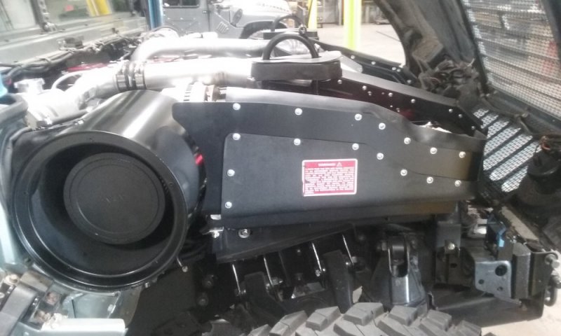
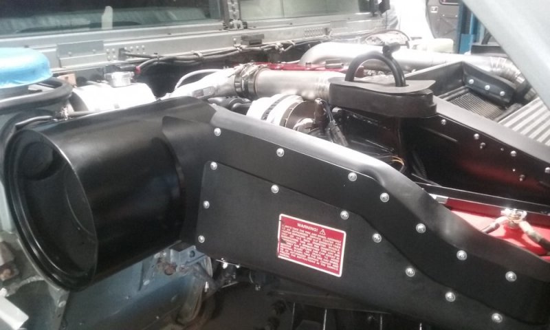
Thank you for sharing these up-close updates! I love the detail you guys put into your builds. It looks like you guys have way too much fun over there!
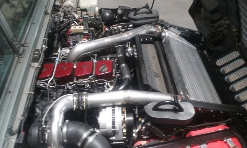
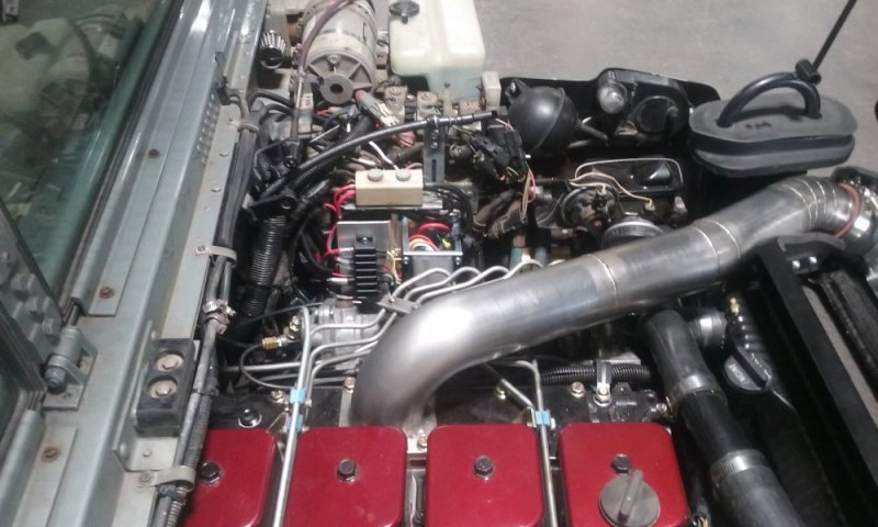
What power level are you running with that H1C?
What power level are you running with that H1C?
Thanks Nate, we scratch our heads a lot and toss out futile attempts before anyone can see them. Ha!
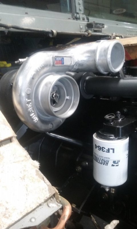
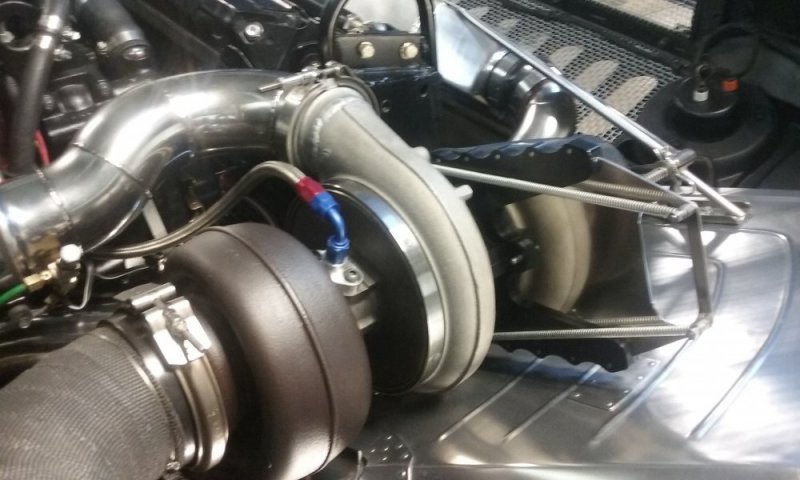
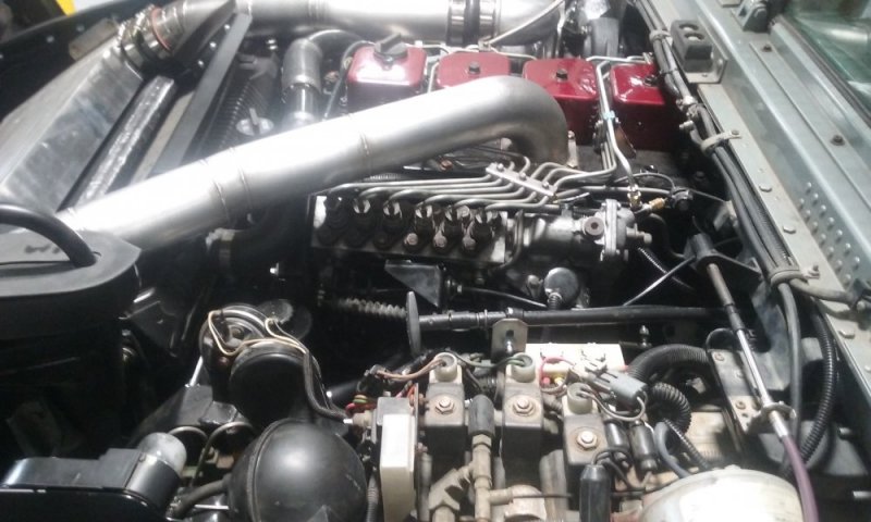
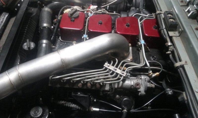
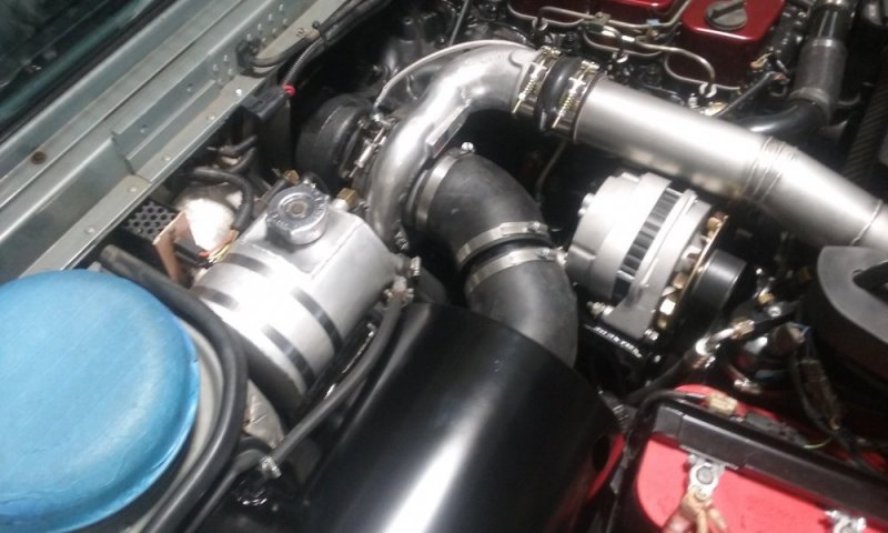
The H1C with the 60 wheel is capable up to a little over 50 lb/min and should be good for 450 to 500 on this motor setup. Nothing outrageous in this one, fellow wants good street manners and reliability.
The H1C with the 60 wheel is capable up to a little over 50 lb/min and should be good for 450 to 500 on this motor setup. Nothing outrageous in this one, fellow wants good street manners and reliability.
Will L.
Well-Known Member
Again, more beautiful work. Can’t wait to see final product.
Of course I had to go back and reread this whole thread spending time zooming in on pics (on my phone is almost all my online stuff) and since have a new 65” tv that can go online, I will be there re examining later today

 .
.
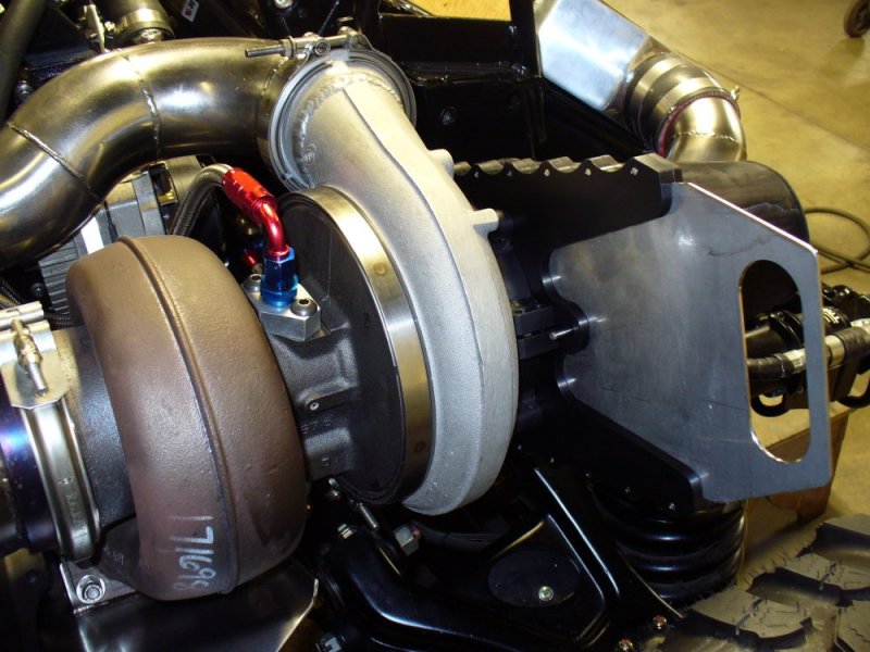
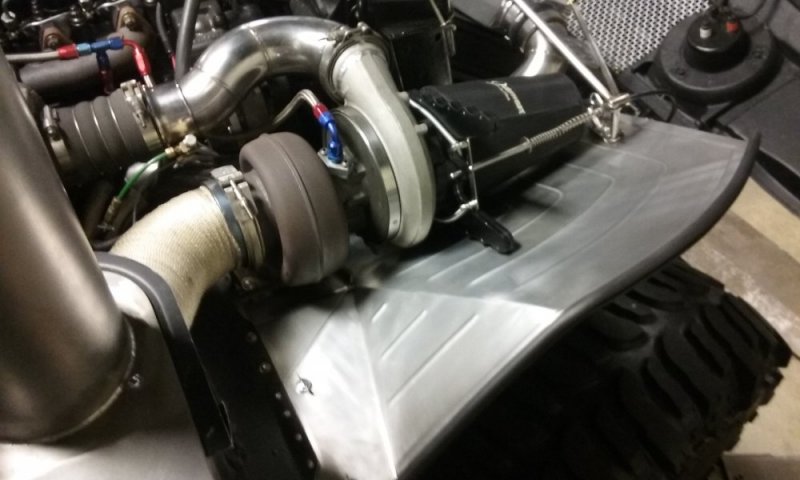
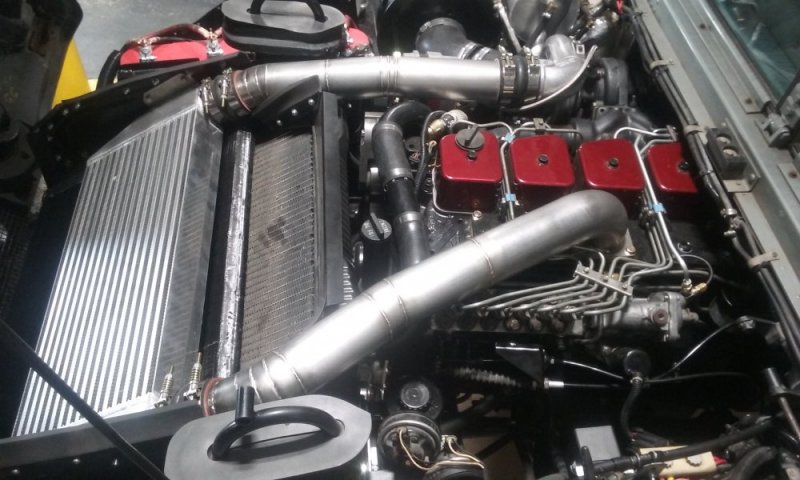
But I have to go back to a questoin on the first build in this pic I zoomed in a bit: is that a safety air shut off valve you all built yourselves after the front turbo? Please share info about that one. Planning on building one myself but that is awesome looking. How I missed it before amazes me.
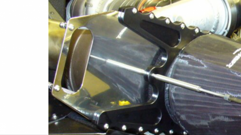
Of course I had to go back and reread this whole thread spending time zooming in on pics (on my phone is almost all my online stuff) and since have a new 65” tv that can go online, I will be there re examining later today
But I have to go back to a questoin on the first build in this pic I zoomed in a bit: is that a safety air shut off valve you all built yourselves after the front turbo? Please share info about that one. Planning on building one myself but that is awesome looking. How I missed it before amazes me.

Yes, this is the safety shut-off. It's a Guillotine style shut off that we designed and built, the pin is connected to a cable that runs into the cabin and has a handle right in front of the shifters for immediate use in the event of a runaway.
We did this after the first almost disaster road test. What had happened was the newly rebuilt P-Pump was not completely cleaned of chips and burrs after the shop did the upgrade to 13mm and the rack stuck. It took 3 miles and 2 ran red lights, 4 burned rotors and their pad sets before a stretch of rough road jarred the rack loose and we were able to pull off and change shorts.
The speed limit on the stretch of road was 50, but the point where you are finished accelerating and let off is where it stuck so the final speed was closer to 65. Luck was with us at the red lights or I wouldn't be typing this.
Things of note here,
1) Use a really good quality shop for all your pump work, don't quip about a few dollars more than Mr. Cutrate.
2) If the motor is running, the alternator is working and back feeding the circuits even with your key off. Put a shut-off in the line if you are running an electric fuel shutoff solenoid, or make sure that it is isolated from the circuit when the key is turned off.
3) I used to think that blowing out and running a rinse through all fabricated lines was a given, that's how I was taught working on aircraft with my grandfather, but a lot of people don't. Nor do they realize the little stuff in that line on the upstream side of the filter system will go right in and create havoc.
Will L.
Well-Known Member
That is very similar looking to what I was planning on making- much nicer in finished work mind you as I dont have access to the cnc stuff anymore- haha.
I have been looking at a few different wood working vacuum system “blast doors”. Just spring load and use a cable inplace of the adjustable knob they have. I don’t see springs on yours for closing, but maybe its inside or underneath?
I used to have to have them for going into refineries, but the certified ones are way pricey. Do you guys sell those? If so, how much and is it waterproof? Mine would currently have to be a 4” on the intake side, so waterproof counts more there. On the pressure side like you have is better - as close to intake as possible was the rule for certified units.
We looked at what was out there, couple of nice ones were very pricey and then there were the sheet metal ones for under $20 on E-Pay. We decided to just make our own and after it had been to a few shows were saw a nice copy of it for sale through one of the Diesels houses, just minus the scallops, so it was decided not to offer it.
We had a waterproof seal on the turbo side face, but it proved to be a problem with the sand dust that would accumulate along the gate edges causing it to bind even with the polished stainless face. The tradeoff is that now it can ingest a certain amount of dust, but it snaps shut on demand. This is an item on our "Nut and Bolt" list when prepping for the dunes and it gets tested and cleaned daily when he has it up at the dunes.
That truck is his "Dune Toy", so most of his driving is in the dust bowl.
The inner fender panel we made helps keep most of the mess away.
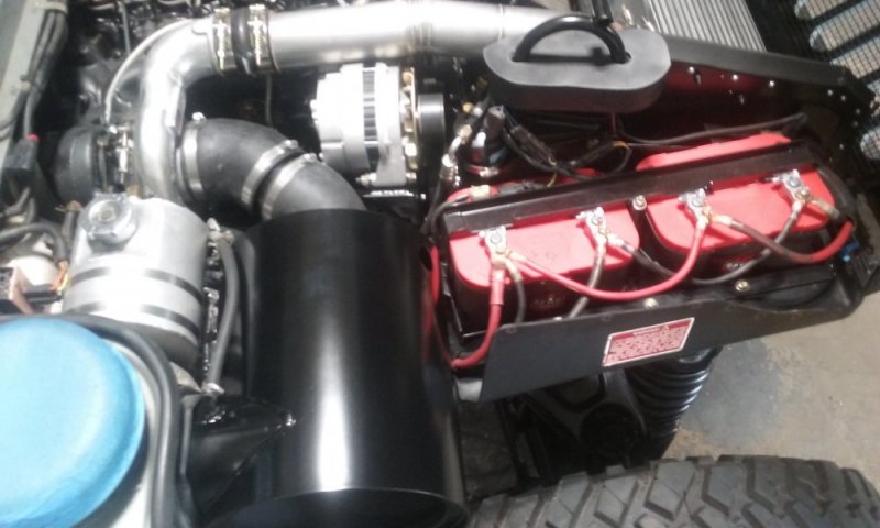
Setting up the motor mount position for the Cummins we use the original crankshaft location and height so as not to change the driveshaft angles. We used the H1 compliance mounts as well.
The setback for the motor location is based on the transmission mount location. Since we mostly use the 4L80e, the mount location does NOT change, the stock location is retained. AM General used an adapter that extends the location back 2 inches from the original location of the T400 mount that would have been centered in the cross member, see the photo.
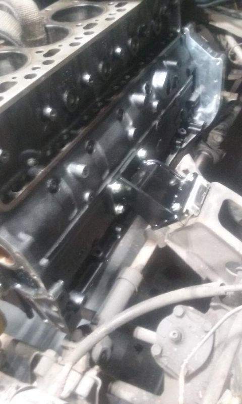
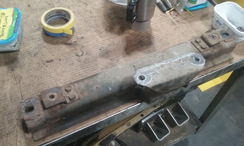
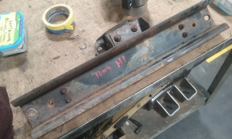
The setback for the motor location is based on the transmission mount location. Since we mostly use the 4L80e, the mount location does NOT change, the stock location is retained. AM General used an adapter that extends the location back 2 inches from the original location of the T400 mount that would have been centered in the cross member, see the photo.


- Staff
- #74
Is that single electric fan all you use for cooling? Have you tried fitting a set of late model camaro fans in there? Have you considered running a 4bt instead of a 6? I would think the extra room would make the swap alot easier, and a properly setup 4bt with twins can make more than enough power to tear up a 4l80e.
FellowTraveler
Well-Known Member
Nice build, I'm surprised your not running a canister filter with a snorkel playing in the sand.
Is that single electric fan all you use for cooling? Have you tried fitting a set of late model camaro fans in there? Have you considered running a 4bt instead of a 6? I would think the extra room would make the swap alot easier, and a properly setup 4bt with twins can make more than enough power to tear up a 4l80e.
The single fan and shroud setup actually works very well. It is set up with a thermal switch and an override in the cabin. We run them with a 195 F thermostat and the thermal switch cuts out at between 165/170.
I know a lot of people seem to have issues and heat problems with their own electric and non-electric set ups, but when you see what they have, then you understand. Lack of shrouding, poor baffling, and I've even seen the hood grill installed backwards on the H1's.
The sand toy runs a dual fan made up of two Ford Taurus A/C fans (they were smaller and fit diagonally). No baffles were installed when we first took it out and it proved to stay too cool running the fans constant. We changed to dual thermal switches, one for each fan and staggered the on/off temps and it handles it quite well. We never added the baffles either.
We have played with the 6.2 and 6.5 Turbo versions and they do seem to run hotter than the Cummins.
Of note too, the Cummins in the sand toy runs 16 quarts of oil, the standard Cummins runs 12. Both have a coolant bypass on the rear freeze plug port.
Not everything in the setups are my choice, I work with the owners and set them up per what they want. You can explain the hazards all day long, but when the have "cool factor" on their minds there is no swaying them. You may be astounded by the thinking, but what comes into play is "I want to hear that turbo spool!" or/and "I want people to hear the Blow Off when I back out of it". Yes, these are actual grown men. Yes, they understand that ingestion of sand will destroy the motor over time. Ha! Know what the answer is?Nice build, I'm surprised your not running a canister filter with a snorkel playing in the sand.
"Well, we can rebuild it, maybe make it even better!"
Sure, why not, gives me something to do.
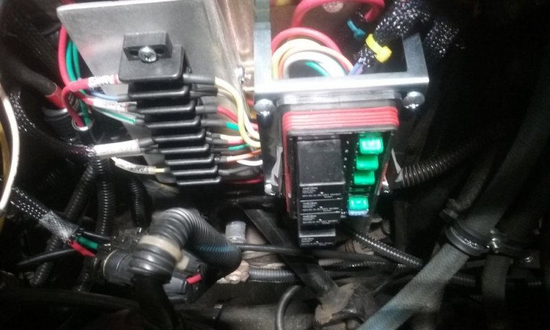
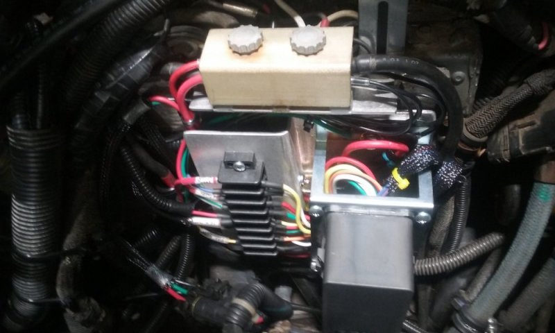
Cummins swaps and the Tach. When I did the sand toy, the wiring in the vehicle had been pretty well boogered up by the previous owners. When I started looking at the Tach installation I Googled around and found everyone opting for manual trans and using the ISSPRO gages, or the induction unit that strapped on the alternator from Autometer. We choose the later.
Since then, I've studied the wiring diagrams and came up with what works using the Crankshaft Speed Sensor on the Cummins and adding 2 additional notches to the harmonic balancer (GM uses 4 pulses).
It's pretty simple, put a 1K ohm resistor between the +12v line (Dodge used +5v and ran to the PCM before the signal was sent to their tach) and the Sense line, Ground to chassis ground and it works no problems.
About the time I was figuring this out I ran across another forum the addressed the same thing. Validation is good.
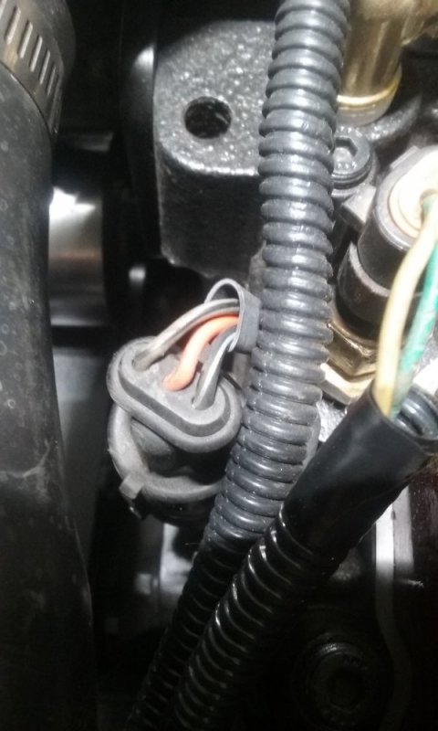
The picture shows the connector and the wires for the CSS. Gray/Blk is the Sense line, Orange is the +12v, and the Blk/Wht line is ground.


