• Welcome to The Truck Stop! We see you haven't REGISTERED yet.

    Your truck knowledge is missing!
    • Registration is FREE , all we need is your birthday and email. (We don't share ANY data with ANYONE)
    • We have tons of knowledge here for your diesel truck!
    • Post your own topics and reply to existing threads to help others out!
    • NO ADS! The site is fully functional and ad free!
    CLICK HERE TO REGISTER!

    Problems registering? Click here to contact us!

    Already registered, but need a PASSWORD RESET? CLICK HERE TO RESET YOUR PASSWORD!

Going mechanical with a Moose Omega Marine IP

Just an fyi, the old Chrysler dual ballast resistor is meant to run a hall effect pickup. All the crank sensor needs is a ground, 12 v+, and a 5 volt reference that can be shorted. The dual ballast resistor had one side for the coil, and the other side was really high resistance for the 5v to a hall effect pickup. Hook 12v+ to one side of the high resistance side of the ballast, the other side of it to the crank sensor, and t in to that wire and you now have a fully functioning hall effect rpm sensor. Some people loop around both sides of the ballast just to play it safe with thecrank sensor. Or you can buy a 5 volt power supply, and a 10k ohm resistor should do the trick for the whortable 5 volt feed/signal. Just make sure the quick 4 can work with a low voltage signal if yougo that route.
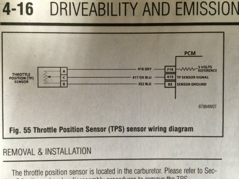
Thanks for the info Ferm. The trans controller has a 5 Volt wire to run the TPS, so I was just going to use that for the 5 Volt reference signal for the crank sensor. Then I was going to use the same ground as the TPS since it's the same circuit. The third wire off the crank sensor would then be my tach signal. That should work, shouldn't it?
 
Thanks for the info Ferm. The trans controller has a 5 Volt wire to run the TPS, so I was just going to use that for the 5 Volt reference signal for the crank sensor. Then I was going to use the same ground as the TPS since it's the same circuit. The third wire off the crank sensor would then be my tach signal. That should work, shouldn't it?
The 5 volt reference is the one that gets pulled to ground for a hall effect sensor, so everytime the sensor triggers, you would lose your 5 volt reference. Even if you install a 10k ohm resistor, it will still probably mess with the 5 volt reference signal, and give an a/c current backfeed in.
 
The 5 volt reference is the one that gets pulled to ground for a hall effect sensor, so everytime the sensor triggers, you would lose your 5 volt reference. Even if you install a 10k ohm resistor, it will still probably mess with the 5 volt reference signal, and give an a/c current backfeed in.
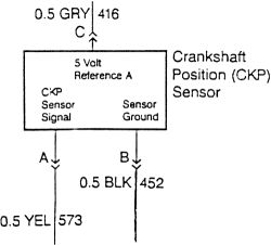
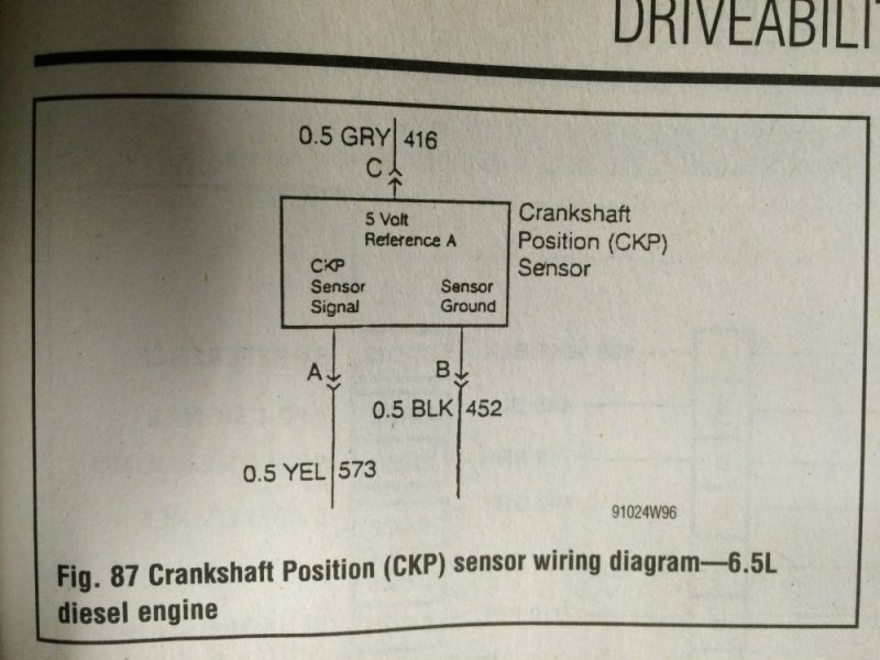
I'm still kind of confused, sorry. I was going off this schematic that's in my manual. image.jpeg
It seems pretty cut and dry how it would work and technical support said that should work based on some other mechanical diesel installations they've done using hall effect crank sensors. But perhaps it's a difference of how the computer uses the signal and not how the Quick 4 does? You can custom set up the tach signal in the Quick 4 to accomodate different signals, but I may just not get it.

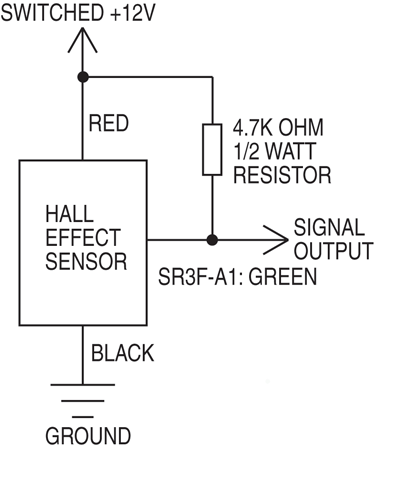
I also found a schematic for what you're describing so I do see what you are saying. image.gif
So I suppose I should go that route. What's an application for one of those resiators?
 
I just pulled up the diagrams, and you're right. I was going off of how Chrysler did there 3 wire hall effect sensors which was COMPLETELY different. They worked on 12 volts, and the output was a switched 5 volt signal.
 
Bracket updates are done. I made a bracket for mounting the Baldwin filter base and the new header/turbo brace. I cut the intake end off the old brace and made a new end to attach to the header flange. Then I welded them together at the appropriate angle. If something there breaks....then I have some REAL problems. Time to start doing cables.....

View attachment 47848 View attachment 47849 View attachment 47850 View attachment 47851 View attachment 47852 View attachment 47853 View attachment 47854
Excellent fabrication, can hardly wait for you to light it up and give feedback on the results.......
 
Power distribution block 001.JPG
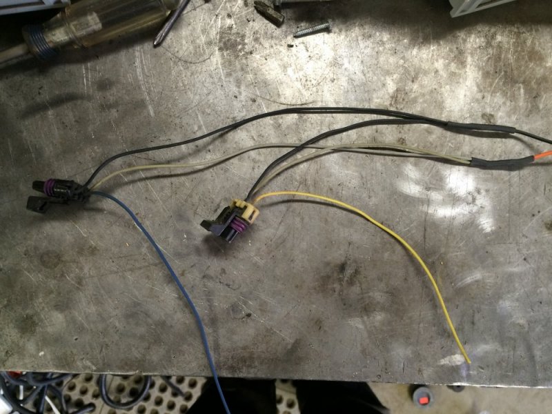
Not too much more to report. I talked with Baumann's technical support about the tach signal for the Quick 4 controller. The guy on the phone (his name was Kevin and he was SUPER knowledgable and SUPER helpful) told me that the tach signal is optional but it enables some neat features that they developed just for the Quick 4. So we talked about how I could use the existing crank sensor and came up with what I think is going to be a slick solution. I'll share those details when I do the wiring so I can add pictures to the details. So after the call I ran to the junkyard to get a pigtail to hook to the crank sensor. Oh by the way, the crank sensor has the same plug as the 93 TPS sensor, so you don't have to try to find a relatively rare pigtail for the TPS, you can instead use a crank sensor one that is on any 94-00 6.5 truck.

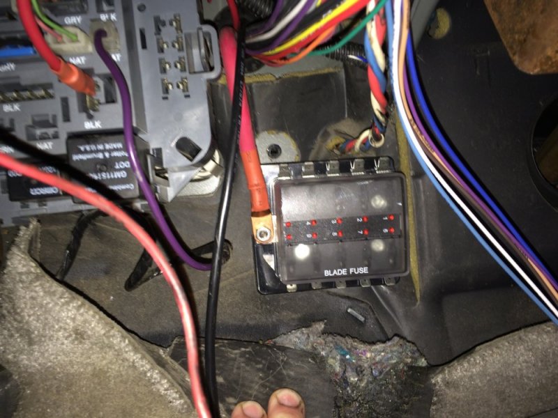
After that I started working on other electrical upgrades. I got tired of never having a good keyed 12V power supply available so I am adding a fused distribution block running off a relay so I'll always have an easy way to add switched & fused power when I want it. I'm going to add a second distribution block under the dash running off the same relay. The relay is rated at 150 amps continuous, so it won't be a problem.

I'm going to call it a day. More tomorrow.
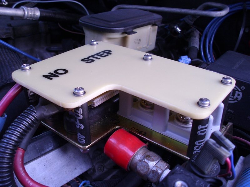
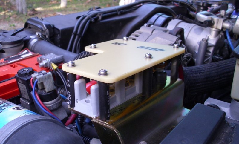
How's this for power distribution over kill, it's surplus from the HMMWV & a whopping $30. if you have the room... Power distribution block 002.JPG View attachment 47862
 
I just pulled up the diagrams, and you're right. I was going off of how Chrysler did there 3 wire hall effect sensors which was COMPLETELY different. They worked on 12 volts, and the output was a switched 5 volt signal.
Oh ok, thank you for spending the time to make sure I wasn't going down a wrong path Ferm.
 
ESS will also give 4 pluses per rev.
Yep. You can enter that value in the Quick 4 set up and it will account for that. We had also talked about using the tach signal off the alternator, but that didn't seem as practical to do.
 
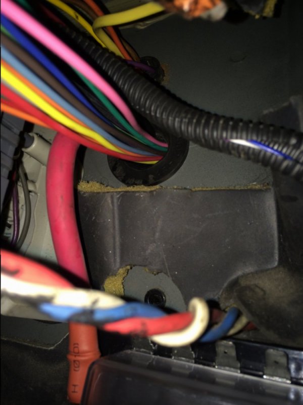
Well, some home stuff came up today so I only got about 5 hours of play time today. I did make some good progress though. I got the second distribution block mounted under the dash. I then drilled the hole in the firewall to run all the harnesses. The largest plug for the trans controller was over an inch wide which disappointed me a little - I didn't really want to drill a hole that big in the firewall but it was what it was. Luckily I had a grommet for a 1-1/4" hole so that worked. In the end I was very happy to have a hole that large because I had a lot of stuff to run through it! Granted some of that was the #4 wire I ran to power the distribution block, but still, it's a lot of wire.

image.jpeg image.jpeg
 
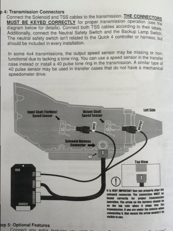
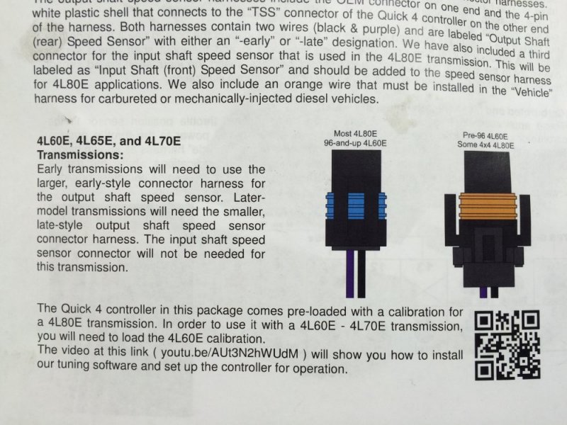
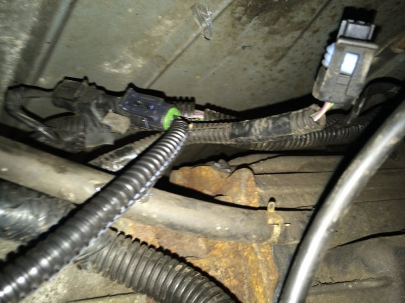
Next it was time to run the trans harness. There was some momentary excitment regarding the rear output shaft speed sensor, but due to some cleverness on GM's part it actually worked out well. There was a note in the Quick 4 manual saying that some 4x4 transmissions don't have a rear sensor and the sensor is actually located in the transfer case. Sure enough, that's where mine was. No big deal, except the t-case sensor had a different plug! Then I noticed a jumper in the harness that was about in the correct location for the rear sensor on the trans and it had the right plug too. So I got out the VOM and sure enough there was continuity so it WAS a jumper for the t-case sensor! So it ended up being a simple plug and play after all.

image.jpeg image.jpeg image.jpeg image.jpeg

This picture shows the controller plug (the one with the green end) plugged in the bypass and the original GM plug (the one with the blue seal) hanging out nearby.
image.jpeg

I then proceeded to do the rest of the wiring for the controller. The main thing to note is what I did for the TPS and crank sensor. Both sensors get a 5V input and have a ground....and those are even color-coded the same which made wiring easier. Then all that was left in the engine was to match up the 3rd TPS wire with the TPS signal for the controller and the 3rd crank sensor wire with the tach signal for the controller.

image.jpeg image.jpeg image.jpeg

Then it was just a switched 12V and a battery ground. I still have some other wiring to clean up and the fuel gauge to install plus some other clean up items.....having said that, if everything goes well I just MIGHT have this thing running tomorrow. Fingers crossed.
 
Nate, fill it with some Silicone to keep mice out.
Oh I definitely will Leo, I just hadn't gotten that far yet. Sometimes I regret posting on here because you eagle-eyes people don't miss a thing! :watching::D
 
  • Like
Reactions: NVW
Does the optishift have a speedometer driver circuit in it? Otherwise you won't have a speedo. That jumper goes from the normal transmission output speed sensor back to the speed sensor in the transfer case. If you unplug it, hook the jumper harness to the OPTISHIFT, then you will no longer have a speed sensor signal going to the VSSB for your speedo, radio, or ABS. Not sure if you can run both the VSSB and the OPTISHIFT off of the speed sensor signal or not. Or if you can use the VSSB output to the OPTISHIFT to make it work that way. Also make sure to hook up the 4 low signal to your OPTISHIFT so you can setup your 4 low input and seperate shift table for 4 low.
 
Does the optishift have a speedometer driver circuit in it? Otherwise you won't have a speedo. That jumper goes from the normal transmission output speed sensor back to the speed sensor in the transfer case. If you unplug it, hook the jumper harness to the OPTISHIFT, then you will no longer have a speed sensor signal going to the VSSB for your speedo, radio, or ABS. Not sure if you can run both the VSSB and the OPTISHIFT off of the speed sensor signal or not. Or if you can use the VSSB output to the OPTISHIFT to make it work that way. Also make sure to hook up the 4 low signal to your OPTISHIFT so you can setup your 4 low input and seperate shift table for 4 low.
Wow, thanks for that catch Ferm. Yes it does have a speedo output, but I think I'll try making a Y adapter so I can plug both the Optishift and the VSSB into that plug. If that doesn't work, then I'll try something with the speedo output.
 
Does the optishift have a speedometer driver circuit in it? Otherwise you won't have a speedo. That jumper goes from the normal transmission output speed sensor back to the speed sensor in the transfer case. If you unplug it, hook the jumper harness to the OPTISHIFT, then you will no longer have a speed sensor signal going to the VSSB for your speedo, radio, or ABS. Not sure if you can run both the VSSB and the OPTISHIFT off of the speed sensor signal or not. Or if you can use the VSSB output to the OPTISHIFT to make it work that way. Also make sure to hook up the 4 low signal to your OPTISHIFT so you can setup your 4 low input and seperate shift table for 4 low.
If the Y harness doesn't work then I'll pop that cap off and see if the tone ring is in the transmission. If so, then I could put a 3rd speed sensor in that location. I'd probably run the VSSB off of that sensor because it would be less important for the ABS and stuff to work in 4 Lo than it would be for the trans to work properly.
 
Back
Top