• Welcome to The Truck Stop! We see you haven't REGISTERED yet.

    Your truck knowledge is missing!
    • Registration is FREE , all we need is your birthday and email. (We don't share ANY data with ANYONE)
    • We have tons of knowledge here for your diesel truck!
    • Post your own topics and reply to existing threads to help others out!
    • NO ADS! The site is fully functional and ad free!
    CLICK HERE TO REGISTER!

    Problems registering? Click here to contact us!

    Already registered, but need a PASSWORD RESET? CLICK HERE TO RESET YOUR PASSWORD!

DB2 Throttle Pedal Resistance

Nice, your giving me ideas now LOL. the thought of possibly using a small flat washer or flat slug grinding with the drimel for the center slot and shaping the outside to fit into the GM tps might work. not sure if I will need to use a couple of flat washers behind the tps to space it out enough for it all to go together or not. but a carved out flat slug might work. maybe a dime or nickle would work. a knock-out from an old electric box too.
 
LOL sometimes we gotta think outside the box HAHA!
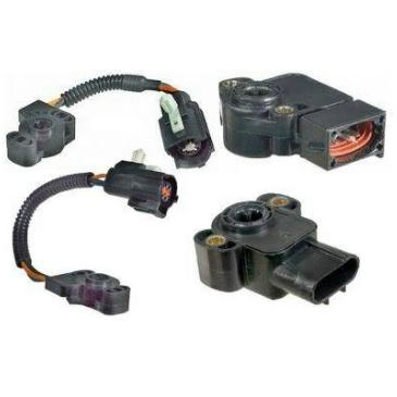
Does the TPS have to be from a truck ?
Seems a TPS is a TPS. They all do the same thing. 12 volts, 5 volt refrence and ground. A change of the plug on the end of the TPS harness fixes that.
Then there might be a simpler solution to whats needed to drive the TPS.
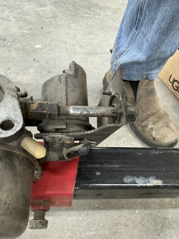
I really do not remember what shape that 3/8ths bolt needed to drive that TPS buf I am guessing it most likely was a screw driver slot affair.
 
I had to take another look at the first picture. I thought that pin was more visible but You have to take a second look to see it.
Drove through that brass nut, to the left side of the brass nut. It is visible but just have to take an upclose looksee.
Thats what kept the brass nut connected to the throttle shaft.
IMG_0765.jpeg
 
That is true, any TPS should work and give the right signal so long as it starts out at 0v and goes to 5v not the other way around. might have to visit the JY soon and take up a collection of them and their pigtails.

also didn't think about candle wax. maybe this weekend I might try pulling the intake and see if the one I have will work and have room to fit a hand made adapter. even if I have to space one out some I think there is about and inch of room before it would make contact with the intake.
It was relatively simple building that setup for the SU carbs.
If needed I can send You what I have here.
I’ll never use it again.
When I do convert to EFI on the MG it will be the Patten Machine Products complete setup.
 
Let me see what I come up with on adapting this one. it's just a "see if I can" thing but LOL I know to do it right I just need to pony up for the humvee TPS :) I found some on ebay I think for around $50 last time I looked. I will look again.
 
Question: I thought the hummer TPS was a two wire unit. looking here on ebay I found several that are three wire. part number 12554488


Not complaining, a three wire makes it easier to use the existing harness and not make an adapter.
 
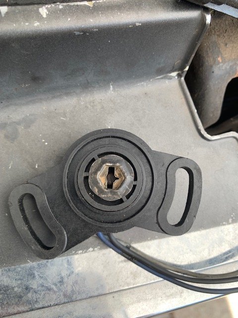
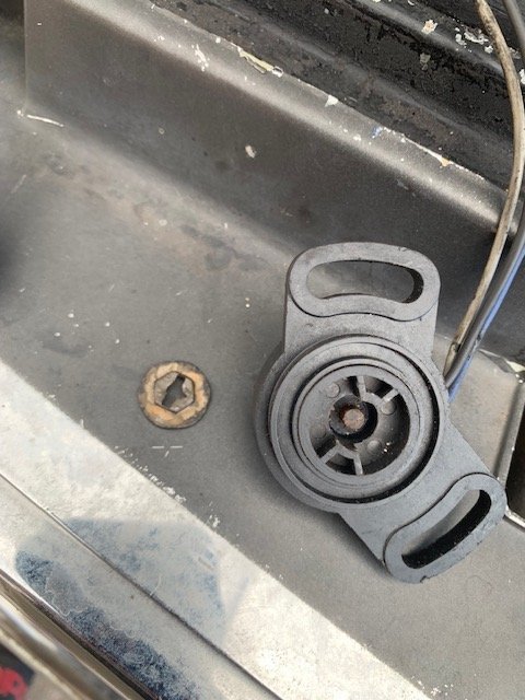
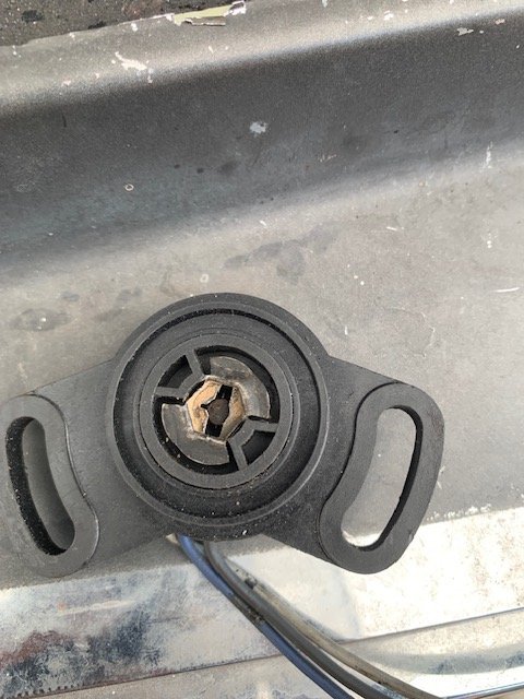
Well, Here is the results of my efforts. I pulled the intake today and ended up using one of those body capture type nuts with a flange to make the adapter. since it was stamped sheet metal it was easy to carve out using my drimel and a small file.

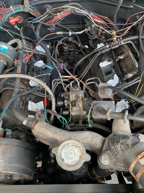
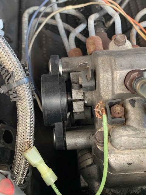
I got it installed, had to space out the TPS slightly but it works. got it semi-wired in enough to test and set. here are the photos.

IMG_5526.jpg
IMG_5524.jpg
IMG_5527.jpg
IMG_5525.jpg
IMG_5529.jpg
IMG_5528.jpg
 
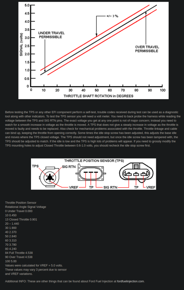
in attempting to set the adjustment as per GM spec, I am finding that the throw the throttle has seems to be more than the TPS. the TPS does not max out at its stop but when setting the idle position at 0.50v I slowly open the throttle and will reach max voltage of 4.88 at a little over 3/4 throttle open. I can continue to open the throttle fully and the voltage remains a 4.88v

I don't know if this is normal or not. I checked the IP on the 6.2 engine which is a GM version and it also has the same throw or amount of rotation.

I had this same issue with the TCI cable driven TPS when trying to set it's limits and is why I kept trying to re-position the cable at the IP. it too would max out on voltage before the throttle was fully open.

testing the GM tps, as I open the throttle it smoothly increases voltage from 0.56 to 4.88 with no glitches, only it reaches full voltage before the throttle is fully open. it's connected to the TCI harness not the factory one, but this shouldn't matter since they both provide 5v signal and a ground to operate it. and I am using my multi-meter to see these readings.
 
I found this online stating something about "over travel" I'm not sure if this is what I am seeing and is normal. @Will L. Have you run into this when setting and testing a TPS?

1728680948776.png

 
Well I think I have found the issue here. removed the cruise cable and throttle cables. both seemed to travel with ease, I lubed them anyway with some dry lube. what I found was when I completely removed the return spring from the IP. the end looked as though it had been re-shaped on the hook. I pulled the return spring on the 6.2 I have on the stand and immediately found that the one on the truck was about 1/4" shorter than the unmolested one on the 6.2 engine.

Installed the spring from the 6.2, this along with the extra resistance from the cable controlled TPS from TCI was causing the stiff pedal. Now it seems "normal" to my foot!!

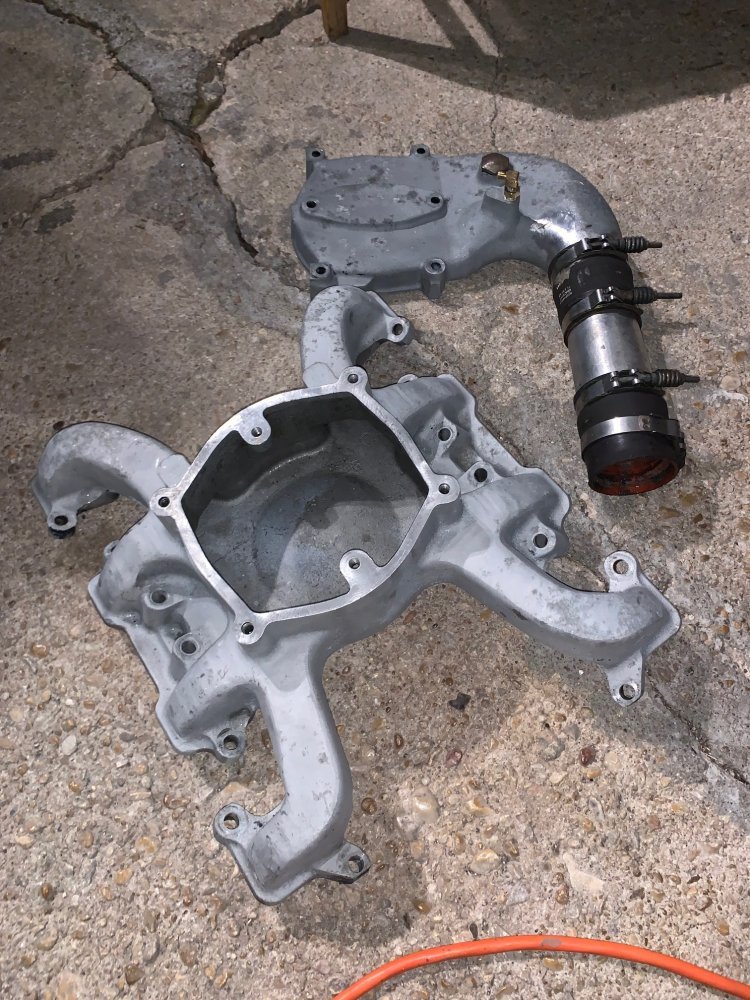
While I have the intake off, I want to replace the fuel hose to the IP that lives under the intake and clean things up a bit and tidy up the wire loom. might even use some paint strip on the intake to remove the black paint and bring back the aluminum color. I'm not going to get to the valve cover gaskets yet though. the drivers side was leaking but last week I snugged up the bolts which were only finger tight, that seems to have slowed the leak to a minimum now. the cam position sensor aka oil pump drive cap that's not in use is leaking but I am afraid to touch it thinking about that plastic union thingiemobob that joins the shaft with the oil pump breaking. I think I will leave that alone. Unless someone chimes in telling me it's safe to pull and use the non sensor drive that's on the 6.2 engine.
 
Finished stripping the black paint off the intake, now I need to get ready to reinstall.

Not sure if I should leave it bare or spritz some clear rattle can over it. the upper intake has some blemishes on the aluminum. thinking about taking the wire wheel and giving it a shine. again it's gonna get dirty and oily again so I probably should leave it alone and bare.

IMG_5532.jpg
 
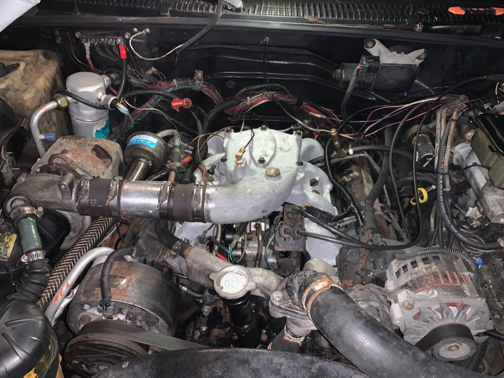
Just finished getting it all back together. need to test some of the wiring I re-did yet. I re-did the complete harness for the TPS and CPS since the connectors were right next to each other. I had previously grabbed 5v from the factory PCM to power the CPS, now it's tied into the 5v feed from the TPS which comes from the TCI tcu. Now the factory PCM should be completely isolated and out of the equation.

IMG_5533.jpg
 
Under and over travel is just saying out of parameters. On the 6.2/6.5 it has alw been just set it to 5.0v at full throttle then check idle is within range.
To be fair, checking it all along the range is the best to know it isn’t having a hiccup along the way but I just slowly move throttle from idle up, then back down and watch that it is a “smooth” transition. I can’t remember getting detailed enough to check exact numbers unless there was an oddball problem in the rig. In my experience tps is either spastic, wrong at idle or wrong at wot. Never had tk be that accurate. But my work is usually crazy old rig so a new one does it or it’s fine. Super rare failure point imo.

On the aluminum intake- I always just clean them up but they always end up grimy later. I was thinking about painting mine this time. It I was rich and fancy I would like to have one made of plastic that newer rigs all use to stop heat intrusion.
Ok, really I wish I could buy that wazoo one with the build in water intercooler Chris sells. But since I am awake enough I need to stop dreaming….😂
I have been using quite a bit of that Rustoleum HAMMERED paint.
Paint and primer in one.
Looks great and seems to hold up well.
If You get some, try it on some other object. Let it cure out well then try the compoment in a grimy environment and see how well it holds up.
 
I did some more modifications to the GM TPS. I was having to use some flat washers behind it to space it out from the IP as the throttle shaft would contact the tps before contacting the IP housing where it mounts. today I pulled the tps back off and gave it a good look. there is a small plastic titty protruding through the center of the tps that seems to be part of the outer housing as it does not rotate with the innards. I took my drimmel and ground it down just a tad. now it's a smaller titty lol. Now it mounts flush with the IP housing and works with the adapter I made.

the drawback is the adjustment. it's maxed out on the adjustment one way for it to not set off a code in the EZ-TCI controller but when moving the throttle it reaches max voltage between 1/2 to 3/4 open throttle. I tested this with the tps in hand turning it and watching the data on the display for the tcu. I had this same issue with the cable driven tps this is also after calibrating the tps with the tcu. I am wondering if this is part of why the trans shifts hard from 1st to 2nd.

On a GM PCM / TCU the TPS helps in telling the trans what pressure to be at not sure if this is true for the EZ-TCI as they are not willing to send me any technical data on this.
 
If someone happens to have a humvee TPS where they can test it's voltage output as it rotates on the IP I can confirm if ordering a humvee TPS will solve this issue of it reaching 5v before the IP is WOT.
 
Back
Top