• Welcome to The Truck Stop! We see you haven't REGISTERED yet.

    Your truck knowledge is missing!
    • Registration is FREE , all we need is your birthday and email. (We don't share ANY data with ANYONE)
    • We have tons of knowledge here for your diesel truck!
    • Post your own topics and reply to existing threads to help others out!
    • NO ADS! The site is fully functional and ad free!
    CLICK HERE TO REGISTER!

    Problems registering? Click here to contact us!

    Already registered, but need a PASSWORD RESET? CLICK HERE TO RESET YOUR PASSWORD!

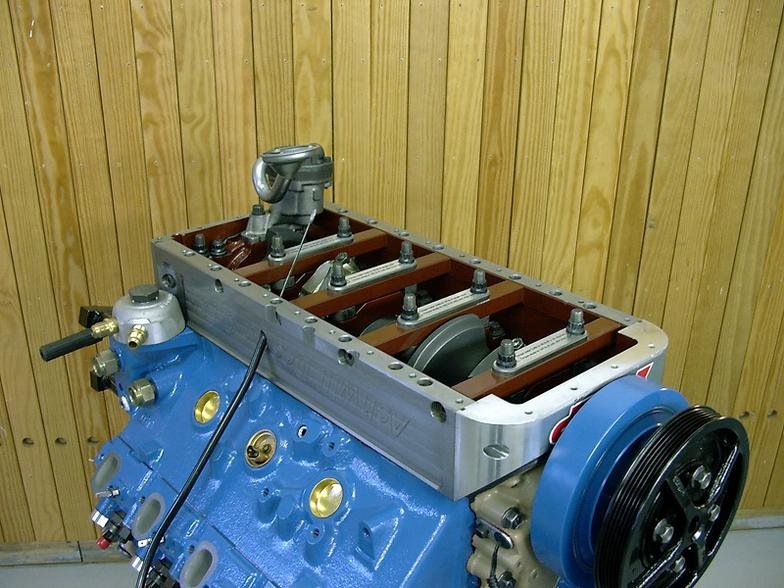
ARP main stud instructions

Mine. '08 block.
Problem is nobody checks for cracks inside the crankcase until their next rebuild so nobody can prove beyond reasonable doubt that it was over torquing of studs that caused the web stress crack(s) and not engine imbalance or harmonic balancer neglect.
 
Last edited:
Mine. '08 block.
Problem is nobody checks until the next rebuild so nobody can prove beyond reasonable doubt that it was over torquing of studs that caused the web stress crack(s) and not engine imbalance or harmonic balancer neglect.
Interesting. I'll be tearing my 04 down in about a month. I beat on it for 2 years with lots of fuel thrown at it and the DSG girdle installed. I'll definitely report my findings.
 
I have talked to several folks that have had failures in the main cap areas, several have pulled the threads out of the block torquing them as they were told to, they then asked me what could be done to fix it... LMAO :banghead: I haven't seen them in person but with a already weak bottom end and shallow tread depth I can believe it.. if a person had the equipment and knowledge the depth of the holes could perhaps be drilled deeper and the threads extended without harming the threads that are already their. Yes it would be something a real machinist would be needed for but similar things are done often, cheap to have done... don't think so, worth the money, again doubtful, debatable at best..

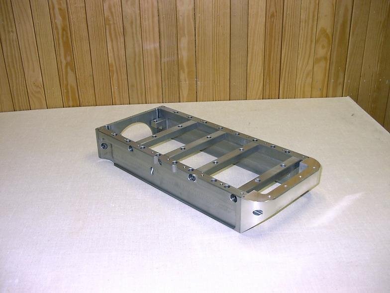
I think the best place to spend time and money would be on laser measuring, cad drawings, machine time to design a full bottom end girdle like the p400 has, costly, yes, saleable, maybe, sell enough to pay for r&d, doubtful... Their is just no way the blocks are strong enough bolting anything solely to the main caps, doesn't matter if you use all 5 or not, the center of the block is just too weak...

Sorry, I've seen too many folks drink the kool-aid then wonder why something didn't go as planed and are told THEY did something wrong...
 
Sure is awesome. If there is anymore about this, please share it.

I appreciate the solutions to the rear main cap- great idea. I would expect the 4 cross members and the rear angles are not secured to the exterior until all the mains are fully tightened. Then attach the frame to them.


gonna go side track more about girdles a minute...
Milling the top of the maincaps so they are all identical height is best but easy for this and should be for even the angle iron 3 or 5 hole setups imo. Especially because you should align hone or align bore after studs or girdles get added anyways. This is because that added tension can alter the block on the micro level, and we are dealing with micro on journals- plus the straighter it is the less chance of braking things. So to start with trimming the top sides to same height is super easy in a machine shop or at home.

At home, place all the main caps touching each other in order on a verified flat with machinists straight edge plate of steel maybe 3/16 or thicker. Mark all 20 holes and drill. Bolt caps to plate w/ all 20 and tighten.
Remove 5 bolts along one side closest to crankshaft. Grind; file; block sand; whatever you have- until they are perfectly flat with a machinist straight edge. Keep in mind level plane to the base plate they are bolted to. Mic the end heights to compare equal height. reinstall & tighten those 5, then repeat on the 5 on the other side of the crankshaft. Then repeat doing outside row, never having more than 5 out at one time.
Now the ever important rule of breaking the sharp edges once removed from the plate.

Obviously you will not get it as perfect as a machine shop and it will be time consuming. But you will have it amazingly closer than the idea of spacers and shims to fill the gap.
 
If i were to take something like this on i would do away with the stock caps, build the outside from steel and design new caps that bolted down from the bottom and sides. It would require a little more real machine time but would be much stronger for a small amount more money. Then a accurate line bore could be done along with a short fill on the block.
 
My next thing is trying to chase down an enerpac RCH302 or RCH306. If anyone has one of these laying around they wouldn’t mind renting to me for a little while please let me know.

similar would work but need around 5 in.² up to 8 in.² of affected cylinder area.
Any if you ebay masters out there find a good china knock off?
 
I also need to buy a couple new main bolts and main studs (one of each size) for the testing. If anyone feels like sending me them, it wouldn’t hurt my feelings. Haha
 
My next thing is trying to chase down an enerpac RCH302 or RCH306. If anyone has one of these laying around they wouldn’t mind renting to me for a little while please let me know.

similar would work but need around 5 in.² up to 8 in.² of affected cylinder area.
Any if you ebay masters out there find a good china knock off?

Dang! Those cylinders are spendy! No wonder you didn't go right out and buy one or three.
 
Haha, yup! Champagne taste on beer budget is the expression, but my budget is closer to koolaide.
Heck man, I`m so broke, if it cost a nickel to get the bathroom door open, I`d have to stand around and grind um out. LOL
Thats what a friend asked Me one time when I cut a big one. You going to go to the bathroom and get rid of that or, are You going to stand around and grindum out. LOL
 
I dont know.
The clamp force applied by torque is what I am trying to learn.
all I can do is assume it is similar force applied by the comparison in the video.
Ours are 12mm bolts and newer engines use both 12mm and 10mm. This video is testing cummins head studs- what I found is also 12mm bolts. I do not know if the thread pitch of the nuts are the same or not 100% but I bel

I plan to replicate what they did in the video using a factory main cap bolt and tighten to spec. Record the number in hydraulic pressure then transpose to clamping force.

Then tighten the arp stud, recording hydraulic pressure as tightening torque increases. This will create a graph showing clamping force at intervals in relation to torque on the nut.

My goal is to know at what torque does the arp nut apply the same clamp force as the factory bolt for both 12mm and 10mm sizes. Added clamp force to the mains applies more stress to the block adding to the cracking problem. A certain amount of added clamp force is better to stop cap walk, but at the risk of cracking mains. Far more people loose 6.5s to cracked mains than cap walk issues.

Their test had ARP max at 152 torque, 2600psi so the math is 18,772 pounds clamp force
And the other brand max torque hit 150.5, 2800 psi so 20,036 pounds force.
Different lube, (possibly different thread pitch of nut), difference in stretch all attribute to different force applied. (Stock bolts for that application are from 13,000-16,000 btw from different source)

Someone better at math than me with more research could determine several ways to do this with more options and could use different sized cylinders and pressure gauges and pumps to do it with. I am horrible at researching the information. Outside you my best current hope is a mfr on ebay and amazon that sells chinese rams so I am awaiting a response on affected cylinder area of thier units to see if theirs will work with what pump and gauges I bought.

I am simply copying what they did in the video using a ram with 7.22 area. That is why I went to those two units. And with a center hole of 1.31” I can buy 1.25” cold round stock, drill and tap threads, weld to a plate of steel (preference of 1.5” or thicker but smaller should work).

With you having the cylinder my first thought was if you do the test if you work with them you have all the hydraulic components available. But if a fastner fails, or if the adapter to hold the fastener fails, that could injure you or someone around you and I can’t put my welding or an exposed fastener to risk someone else.

Knowing failure point of bolt & stud would be interesting, but a waste of time imo. I believe we have all seen cracked main webs. I have yet to see a bolt failure. It is possible they stretched allowing freeplay of the caps, then crank snap. In the racing world it happens, but is easily identified. When your block and or crank is broke and the bolts were still tight - it wasn’t bolt failure.

If I had a couple engine blocks I could ruin- that would be well worth it. Rip out some main studs and head studs- yeppers- that would prove some stuff too. So if anyone want to ship a block to me- haha. I WOULD NOT DO THAT WITH A BORROWED RAM. If I buy one I would. Or if I rent one from a local store that has insurance of damage insurance at affordable price- yup. It would be super amazing to do a red 6.2 and newer 6.2. Then a couple years of 6.5 and the optimizer.
 
One time the DOT had a class on clamping force of nuts. It showed that a nut holds by 1-1/2 threads at the middle of the threaded range in the nut. It also showed that if a nut is used once then used once again, the clamping force was not near what it should be upon subsequent use.
Below is from Fastenal web page.

On a demonstration with a 1/2-13 zinc plated SAE J429 Grade 5 hex cap screw and zinc plated SAE J995 Grade 5 hex nut with an installation torque of 70 ft-lbs to obtain a clamp load of 9000 lbs (without any added lubrication). On the second installation, this torque had increased to 95 ft-lbs to obtain 9000 lbs. By the fourth installation, we required 145 ft-lbs to reach a clamp load of 9000 lbs.


There are a number of clear indications that the fastener should not be reused, however typically the decision comes down to the economics of the fastener(s) vs. the cost of a failure of the fastened assembly.
 
Back
Top