• Welcome to The Truck Stop! We see you haven't REGISTERED yet.

    Your truck knowledge is missing!
    • Registration is FREE , all we need is your birthday and email. (We don't share ANY data with ANYONE)
    • We have tons of knowledge here for your diesel truck!
    • Post your own topics and reply to existing threads to help others out!
    • NO ADS! The site is fully functional and ad free!
    CLICK HERE TO REGISTER!

    Problems registering? Click here to contact us!

    Already registered, but need a PASSWORD RESET? CLICK HERE TO RESET YOUR PASSWORD!

What did you do with your GMT400 today...or yesterday....

I'm guessing I will need to set the torque for less using the crows foot.
.any thoughts on a good setting?

The crows foot I have is line wrench style like these.

That would depend on where the end of the crows foot would be.
I do know that there are formula for such devices but I cant remember where I had once seen them.
Every inch out needs to be reduced in torque value and if the device is pointed inwards towards the handle then torque value needs to be increased.
Kind of like adding an extension to a torque wrench, there is formula for that too.
 
Morning everyone.Here are the finishing touches regarding the wiring for the fuel pressure gauge.I used 3 fuse taps which turned out pretty good.I had to use some permatex liquid electrical tape I found at Napa on the small gauge wires after I crimped and heat shrinked them going into the fuse taps.I figured some wire loom would be good to use as well.

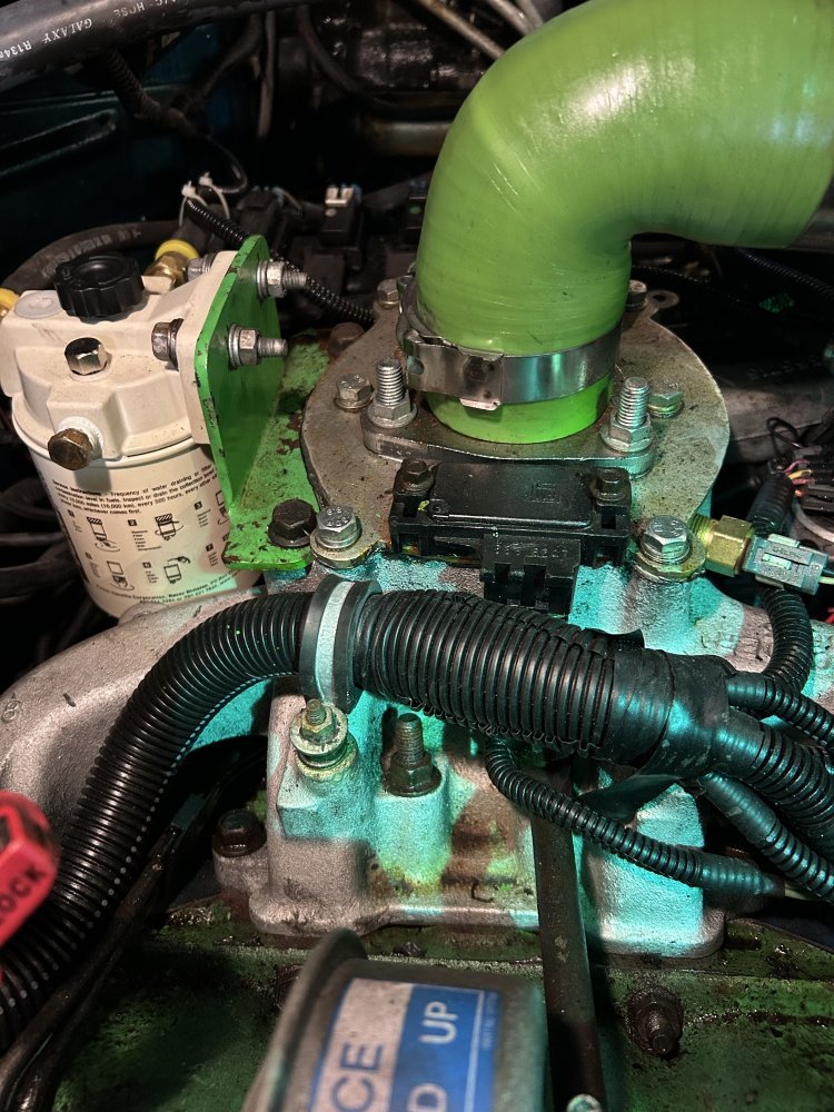
And here are some pictures of the intake system I modified a few years ago.I drilled and tapped two small holes for the boost sensor I think it’s called?And of course a larger hole was drilled to allow the plastic nipple on the sensor to go down through the steel plate.A paper gasket and silicone was used to seal the steel plate against the intake manifold.And the 3 hole flange has a gasket under it as well.

The rest of the intake just comprises of silicone couplers and elbows I got from eBay along with the clamps.The steel pipe I found at a local exhaust shop which turned out pretty well.Here are a few pictures of how everything looks.
 

Attachments

  • IMG_7632.jpeg
    IMG_7632.jpeg
    173.5 KB · Views: 19
  • IMG_7635.jpeg
    IMG_7635.jpeg
    147.6 KB · Views: 18
  • IMG_7636.jpeg
    IMG_7636.jpeg
    116.4 KB · Views: 19
  • IMG_7637.jpeg
    IMG_7637.jpeg
    138.9 KB · Views: 19
  • IMG_7634.jpeg
    IMG_7634.jpeg
    173.1 KB · Views: 19
  • IMG_7633.jpeg
    IMG_7633.jpeg
    140.3 KB · Views: 18
That would depend on where the end of the crows foot would be.
I do know that there are formula for such devices but I cant remember where I had once seen them.
Every inch out needs to be reduced in torque value and if the device is pointed inwards towards the handle then torque value needs to be increased.
Kind of like adding an extension to a torque wrench, there is formula for that too.
 
Morning everyone.Here are the finishing touches regarding the wiring for the fuel pressure gauge.I used 3 fuse taps which turned out pretty good.I had to use some permatex liquid electrical tape I found at Napa on the small gauge wires after I crimped and heat shrinked them going into the fuse taps.I figured some wire loom would be good to use as well.

And here are some pictures of the intake system I modified a few years ago.I drilled and tapped two small holes for the boost sensor I think it’s called?And of course a larger hole was drilled to allow the plastic nipple on the sensor to go down through the steel plate.A paper gasket and silicone was used to seal the steel plate against the intake manifold.And the 3 hole flange has a gasket under it as well.

The rest of the intake just comprises of silicone couplers and elbows I got from eBay along with the clamps.The steel pipe I found at a local exhaust shop which turned out pretty well.Here are a few pictures of how everything looks.
I like how you were able to batch the color of the silicone hose and the valve covers and what not on the engine
 
Looked at my mile ticker today and realized I have about 440 miles or so left before she turns 300k

stopped in the auto parts house this afternoon to pickup an outer tie rod end since I noticed it's got a slight amount of slop. Plan to replace it tomorrow sometime.
 
Well it's official! the 93 truck is licensed and on the road. got it inspected and licensed today and took it out for a drive.

almost immediately I was faced with and collapsed passenger side brake hose and the caliper stayed clamped to the rotor! Yipes. babied it to the house and replaced the hose. Back on the road again....

seems to run good other than the engine is clattering louder than my 95 under load, but I have another issue to figure out. the trans is shifting but is shifting really hard from 1st to second. The kind of neck breaking shift! doesn't seem to matter if you slowly accelerate or do it fast. 2nd to 3rd is a little firm and 3rd to 4th still firm but much lighter. Fluid is full and clean, not sure where to start. the truck has a EZ-TCI controller, but I don't have the hand held display to look at any of the settings or codes. I also noticed that under light acceleration or cruising a low speeds, it will shift all the way into 4th at around 40 mph. I am wondering if the TCC is locking up and not unlocking during shifts although it shouldn't be locking in first gear. Honestly I have not way to tell or know how I can disable the TCC just to see if this is the issue.

Curious if anyone would know an easy way to disable the TCC from working just to test this theroy, or if anyone has other ideas to try.

Anyone have experience with a EZ-TCI TCU?
 
could be in limp mode too
Not sure what limp mode does or how it acts with these TCU's I talked to deejaaa and he seem to think the TCC might be locking up. There is a toggle in the dash that will manually lock the TCC. the other day I drive it around the neighborhood and was trying the switches to see what did what. I found the TCC switch, but today while out on the road cruising at about 45 that switch did nothing as if it was already locked in. He did tell me the TCC would not lock on it's own by the TCM, he hadn't gotten that working.

that leads me to think ether that the contacts in that switch went south from sitting where it's now locked in from key on, or wiring to the switch might have shorted on something
 
I had the mind set that if a TCC was locked and you put it in gear, it would immediately kill the engine... from what info I found on these trucks and the 4l80e apparently this isn't the case. the TCC locks down with pressure and fluid circulation from the rotation of the converter. so it wouldn't actually lock until the rpm's are higher. Correct me if I'm wrong, I'm just learning how transmissions work.
 
Not sure what limp mode does or how it acts with these TCU's I talked to deejaaa and he seem to think the TCC might be locking up. There is a toggle in the dash that will manually lock the TCC. the other day I drive it around the neighborhood and was trying the switches to see what did what. I found the TCC switch, but today while out on the road cruising at about 45 that switch did nothing as if it was already locked in. He did tell me the TCC would not lock on it's own by the TCM, he hadn't gotten that working.

that leads me to think ether that the contacts in that switch went south from sitting where it's now locked in from key on, or wiring to the switch might have shorted on something
A step on the brake pedal should disengage a locked up TCC.
 
I had the mind set that if a TCC was locked and you put it in gear, it would immediately kill the engine... from what info I found on these trucks and the 4l80e apparently this isn't the case. the TCC locks down with pressure and fluid circulation from the rotation of the converter. so it wouldn't actually lock until the rpm's are higher. Correct me if I'm wrong, I'm just learning how transmissions work.
TCC should not lockup until the engine temp gets to, IIRC, 175 degrees F.
 
Back
Top