• Welcome to The Truck Stop! We see you haven't REGISTERED yet.

    Your truck knowledge is missing!
    • Registration is FREE , all we need is your birthday and email. (We don't share ANY data with ANYONE)
    • We have tons of knowledge here for your diesel truck!
    • Post your own topics and reply to existing threads to help others out!
    • NO ADS! The site is fully functional and ad free!
    CLICK HERE TO REGISTER!

    Problems registering? Click here to contact us!

    Already registered, but need a PASSWORD RESET? CLICK HERE TO RESET YOUR PASSWORD!

I P not leaking (THANKS)….DS4 1995

panran

Active Member
Messages
94
Reaction score
222
Location
Colorado high plains 6300 feet
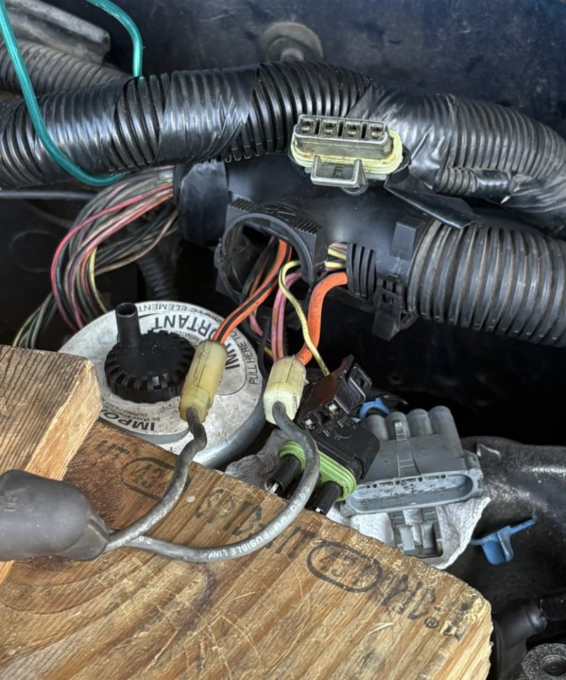
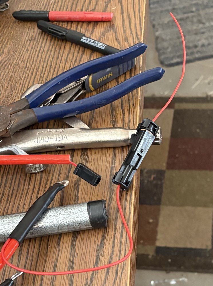
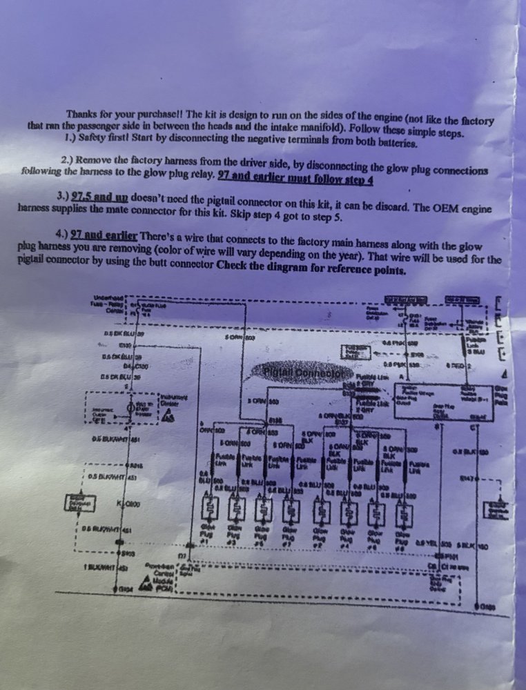
Thank you to everyone for help, tips, and feedback…the engine does run…what a relief! Now start to get it roadworthy. But I do have a question or more in need of advice. When I started the engine I could only plug 6 glow plugs in so there was a little rough start and a lot of white smoke out the exhaust on the 2 cylinder that were not plugged in. So I bought aftermarket glow plug harness thinking it would be plug and play but couldn’t recognize what wire powers the glow plug light. I took pics of what there is and what I’m looking to connect.
 
The new gloplug harness ring terminals hooks to the GP controller on one side. The glow plug control wire ring terminal from the battery side, not literally, hooks to the other side.
That GP harness with the plug connector feeds the GPs on the left side of the engine then that plug connector gets plugged into its other end.
The best way to get the middle two RH GPs plugged onto the harnesses is to remove the two heat shields that protect the GP wires.
Shove the shields over the proper wires, plug the wires to the GPs then slide the shields back over the GPs and fasten them back down with the nuts on the studs.
This all being done with the RH fender well removed is easiest.
 
Thanks..some of the wiring is hacked up…and don’t have the heat shields.. I get the hookup for the right and left side but was wondering about the wire that hooks up to the power from the ignition and triggers the glow plug heat cycle and what color, because the existing plastic wire loom cover is so brittle I was trying not to destroy too much of it.
 
The drivers side GP feed, fat orange wire, goes to the drivers side glow plugs.
Near where it exits the main loom to the glow plugs there will be a splice and another fat orange wire that runs to the fuse box.
Cut the fat orange wire that runs to the fuse box just past the splice and remove the old harness.
You need to connect that pigtail on the new harness to the fat orange wire that runs to the fuse box.
That is what turns on the WTS lamp.
In the second picture, is the wire to be cut the solid orange wire or the wire with the black stripe ?
 
First pic, those solid dark grey wires clearly states that those are fusible links.
I would not even make an attempt to try and make a statement as to what goes where on Your system.
On My 2000 it was a matter of tearing out the old harness and hooking the new GP wires to the controller.
There was no need to chop or hack on any of it.
 
Back
Top