
FUEL SYSTEM
A Robert Bosch CP3 high-pressure fuel injection pump is used. The pump is attached to the back of the timing gear housing at the left-side front of the engine

DESCRIPTION
The fuel system on the 5.9L Common Rail Diesel Engine uses a rotary mechanical fuel injection pump and an Electronic Control Module (ECM) and is a drive-by-wire system, meaning there is no physical throttle cable.
The fuel delivery system consists of the:
- Accelerator pedal position-sensor module
- Air cleaner housing\element
- Fuel filter\water separator
- Fuel temperature sensor
- Fuel heater
- Fuel rail relief valve
- Fuel rail pressure sensor
- Fuel injection pump
- Fuel injectors
- Fuel tank
- Fuel tank filler\vent tube assembly
- Fuel tank filler-tube cap
- Fuel tank module containing the electric lift pump, roll-over valve and a fuel gauge sending unit (fuel level sensor).
- Fuel tubing\lines\hoses
- High-pressure fuel injector lines
- Low-pressure fuel supply and return lines
- Low-pressure fuel return line
- Overflow valve
- Quantity control Fuel Control Actuator valve
- Quick-connect fittings
- Water sensor\drain module
FUEL INJECTION PUMP
The Cummins 5.9L CRD uses the Bosch CP3 injection pump, used also on the DMax 6.6L V8 CRD and the Jeep 2.8L CRD
DESCRIPTION
A radial, 3-piston pump, with a gear-type supply pump attached to the back, is used as the high-pressure pump for common-rail fuel pressure generation - in this system it is capable of pressures between 300-1600 bar (4351-23206 psi) .
A spring-loaded Cascade Overflow Valve regulates internal housing pressure
Regulated internal housing pressure is oem-specific
The pump shaft is driven by the timing belt at 1:1 ratio to the crankshaft.
Fuel pressure is generated independently of the injection process.
A Fuel Control Actuator solenoid valve regulates injection pressure
The injection pump is lubricated by the pumped Diesel fuel and is not responsible for fuel injection timing.
OPERATION
SUPPLY PUMP
DESCRIPTION
The gear-type supply pump has two functions:
- draws fuel from the fuel supply
- increases fuel pressure for regulation to housing pressure required for internal lubrication and supplying the high-pressure injection pump
OPERATION
This fuel system uses a gear-type supply-pump attached to the rear of the high-pressure pump. This medium-pressure fuel pump is driven by the end of the high-pressure injection pump shaft, and can generate greater than 20" vacuum at the fuel inlet at high rpm.
The supply pump is supplied fuel from the lift pump in the fuel tank through the fuel manager\filter.
The outlet of this pump provides pressurized fuel to a branched circuit internal to the high-pressure pump flange, which supplies both the Fuel Control Actuator solenoid valve and the Cascade Overflow Valve\regulator. Because the pump increases fuel flow and pressure as engine rpm increases, it's output pressure and flow is regulated by the COV.
The COV and supply-pump are not serviced independently of the high-pressure pump.
CASCADE OVERFLOW VALVE
DESCRIPTION
The COV is located on the front cover of the high pressure pump.
The Cascade Overflow Valve has three functions:
- regulation of lubrication fuel to the internal moving parts of the high-pressure pump
- regulation of the fuel pressure being supplied to the Fuel Control Actuator solenoid valve
- return excess fuel to the fuel tank
This regulated internal pressure is known as housing pressure, and is determined by engine displacement and power requirements - the 5.9L CRD requires 5-12.4 bar (80-180 psi)
For comparison, the 2.8L 4-cyl Jeep CRD requires 5bar (73psi)
OPERATION
The COV has a spring-loaded center spool-piece that has a drilled channel with three passages: one for initial low-pressure lubrication, one for lubrication at housing-pressure , and one for overflow. The valve is operated in three stages based on the level of pressure at the inlet.
Stage 1
When the fuel pressure entering the tip of the COV is between 0 and 3 bar (43psi), pressure is too low to overcome regulator spring tension and fuel flows through the center channel, only . This passage always allows fuel flow through to the pump center-ring and lubricates the pump bushings and internal moving parts. This circuit also allows air to bleed during initial cranking and returns the air to the fuel tank.
The COV is in Stage 1 during cranking, only.
Stage 2
When the fuel entering the COV exceeds 5bar (73psi), but is less than 12.4bar (180psi), the spool-piece moves against spring tension aligning a second passage for lubrication purposes.
Stage 2 can be reached during cranking and initial start up.
Stage 3
When fuel pressure exceeds 12.4bar (180psi), the spool-piece aligns with the overflow passage. This stage relieves the pressure into an overflow circuit that sends the fuel back to the inlet side of the gearotor pump, thus limiting maximum fuel pressure to 12.4bar (180psi).
Lubrication fuel continues to flow through all channeled passages during this stage.
Excess fuel is sent back to the fuel tank through the fuel-return circuit
Stage 3 is reached at over-pressure
FUEL CONTROL ACTUATOR
DESCRIPTION
The Fuel Control Actuator solenoid valve is located on the back of the front cover of the high-pressure pump. The solenoid is pulse-width modulated by the ECM and meters the amount of fuel that flows into the high-pressure elements inside the high-pressure pump.
The solenoid is inactive up to 30 seconds after IGNition switch is initially keyed to ON position to allow maximum fuel pressure to the fuel rail during cranking and start up. ECM assumes FCA valve control when CPS signal and rail pressure are within acceptable limits
OPERATION
The Fuel Control Actuator solenoid valve is a pulse-width modulated valve that controls the amount of fuel sent or delayed to the high-pressure pump elements inside the high-pressure pump. The ECM determines the fuel pressure set point based on engine sensor and rail-pressure inputs. If the actual fuel-rail pressure is too low, the ECM commands the solenoid to allow more fuel to flow to the high-pressure pump. This minimizes the difference between the actual fuel-rail pressure reading and the set point. The ECM will also operate the solenoid to delay fuel, reducing flow-rate, if the fuel-rail pressure becomes too high.
The FCA valve is commanded open by the ECM to allow the high-pressure pump to build maximum pressure (1600bar, 23,206psi).
Thus, rail fuel-pressure can be increased or decreased independent of engine speed
High Pressure Pumping Plungers
The FQS valve supplies three high pressure pumping chambers. The pumping chambers have one-way inlet valves that allow fuel to flow into the chambers. The valves then close as the fuel is compressed, causing the high pressure fuel to overcome a spring-loaded ball-and-seat outlet valve.
All three pumping chambers are tied together in one circuit internal to the pump and provide high pressure fuel between 300bar (4351psi) and 1600bar (23,206psi) through a steel line to the fuel rail.
The pump is driven at 1:1 engine speed and is not responsible for injection timing.
Pump function is to provide fuel at high-pressure, while the ECM controls injection pressure and timing.
FUEL RAIL
DESCRIPTION
The fuel rail is mounted to the cylinder-head cover\intake manifold. The rail distributes regulated high-pressure fuel equally to the fuel injectors.
A pressure sensor is screwed into the rail so ECM can read and regulate system pressure.
A pressure solenoid is screwed into the fuel rail to allow regulated overflow return to the fuel tank.
OPERATION
The fuel rail stores the fuel for the injectors at high pressure. At the same time, the pressure oscillations which are generated due to the high-pressure pump delivery and the injection of fuel are dampened by rail volume.
The fuel rail is common to all cylinders, hence it’s name "common rail". Even when large quantities of fuel are extracted, the fuel rail maintains a constant inner pressure. This ensures that injection pressure remains constant from the instant the injector opens to the end of the injection event.
FUEL LINES
DESCRIPTION
LOW-PRESSURE FUEL LINES
All fuel lines up to the fuel injection pump are considered low-pressure. This includes the fuel lines from the fuel tank module to the inlet of the high-pressure fuel injection pump. The fuel-return lines and the fuel-drain lines are also considered low-pressure lines.
High-pressure lines are used between the fuel injection pump and the fuel injectors
HIGH PRESSURE FUEL LINES
High-pressure fuel lines are used between the high pressure fuel injection pump and the fuel rail, and between the fuel rail and fuel injectors
All other fuel lines are considered low-pressure lines.
OPERATION - HIGH PRESSURE FUEL LINES
High-pressure fuel lines deliver fuel under extremely high pressure - between 300-1600 bar (4351-23206 psi) - from the high-pressure pump to the rail to the fuel injectors. The lines expand and contract from the high-pressure fuel pulses generated during the injection process, which can delay the injection event - ECM compensates for that based on component specs
All high-pressure fuel lines between the rail and the injectors are of the same length and inside diameter to ensure equal-duration injection events, cylinder to cylinder.
Correct high-pressure fuel line usage and installation is critical to smooth engine operation.
FUEL MANAGER\FILTER
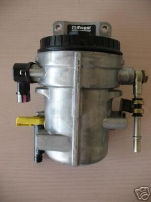
FUEL FILTER / WATER SEPARATOR
DESCRIPTION
The fuel filter/water separator assembly is located on the left rear side of the engine. It incorporates the fuel temperature sensor, fuel heater and a Water-In-Fuel (WIF) sensor.
Only the fuel filter cannister and the WIF sensor are serviced separately. The top-loaded fuel filter has a 3-micron element and the cap tightens clockwise to the housing.
OPERATION
The fuel filter/water separator protects the high pressure fuel injection pump by removing water and contaminants from the fuel with a 3-micron filter element. The construction of the filter/separator allows fuel to pass through it, but helps prevent moisture (water) from doing so. Moisture collects at the bottom of the cannister for draining.
A Water-In-Fuel (WIF) sensor is attached to the fuel filter cannister and is serviced separately.
The fuel heater is in a thermoplastic module inside the fuel manager head - it is not serviced separately from the head.
WATER IN FUEL SENSOR
DESCRIPTION
The WIF sensor is attached to the bottom of the fuel filter/water separator cannister. The sensor also has a drain channel and provision for adapting a drain hose.
OPERATION
The sensor varies an input to the ECM, allowing it to sense water in the fuel filter/water separator.
As the water content in the filter/separator increases, the resistance across the WIF sensor decreases. This decrease in resistance is measured by the ECM and compared to a calibrated standard value. If the resistance drops to a value between 30 and 40 kohms, the ECM will activate the Water-In-Fuel warning lamp. This all occurs when the IGNition key is initially switched to ON position
FUEL HEATER
DESCRIPTION
The fuel heater is used to prevent diesel fuel from waxing and plugging the fuel filter during cold weather operation.
The fuel heater is located in the fuel heater module, next to the fuel temperature sensor - the module is internal to the fuel manager head.
On temperature is 7°C (45° F), off temperature is 29°C (85° F).
OPERATION
The element inside the heater assembly is made of a Positive Temperature Coefficient (PTC) material, and has power applied to it by the fuel heater relay anytime the ignition key is in the ON position. PTC material has a high resistance to current flow when its temperature is high, which means that it will not generate heat when the temperature is above a certain value. When the temperature is below 7°C (45° F), the resistance of the PTC element
is lowered, and allows current to flow through the fuel heater element warming the fuel. When the temperature is above 29°C (85° F), the PTC element’s resistance rises, and current flow through the heater element stops .
Fused voltage to operate the fuel heater is supplied from the Ign switch, through the fuel heater relay, when the ECM senses the IGNition (key) switch is ON.
Sensed temperature for on and off operation is the temperature of the element, which allows full heating only when the temperature drops below 7°C (45° F) - element should not produce full heat on an 18.3°C (65° F) day, for example
ELECTRIC FUEL LIFT PUMP
ELECTRIC LIFT PUMP
The '03-'04 trucks have a Carter sliding-vane type lift pump attached to the Fleetguard fuel manager head on the engine supplying ~15psi - pressure is regulated via internal bypass
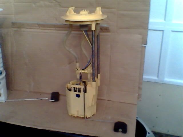
The '05^ trucks have a rotary-vane type in-tank lift pump in the fuel tank module, supplying ~9psi - pressure is regulated via external bypass, returning excess fuel to the tank
DESCRIPTION
The under-hood Fuse Center contains a fuse and solid-state relay for an electric lift pump.
Relayed power is supplied to the pump, which is mounted in the fuel tank
The lift pump supplies 9psi @50gph @ 5amps
OPERATION
Fused power to the solid-state relay is supplied when the IGN switch is in the ON position.
ECM controls the relay in two modes, prime and run - a safety feature helps prevent fire in event of accident or other emergency
At power-ON, during WTS, ECM closes the solid-state relay for 2 seconds to prime the low-pressure fuel system to the Inj Pump - if ECM does not sense pulses from the Crank Position Sensor within 25 seconds or when intake air heater shuts off, the relay is powered down - relay is powered up again when CPS senses crankshaft rotation, indicating START in progress
Power is maintained until crankshaft stops, which is a saftey feature, or when IGN is switched OFF
The CP3 Inj Pump has a built-in gearotor-style lift pump, driven by the pump shaft - it will develop 20" vacuum at higer rpm, and is designed to pull fuel from the tank thru a filter.
The '03-'04 Dodge trucks have an additional Carter-style rotary lift pump mounted on the fuel manager head - those are not flow-thru when fail type, so the CP3 cannot pull fuel from the tank as the electric pump fails - this will leave you on the side of the road, even tho the CP3 could get you home
The '05-up trucks have an in-tank electric lift pump that runs at a constant 9psi - it flashes toward 30psi at key-on, then settles back to 9psi as the CP3 bypass begins to function - it is a rotary-vane type externally bypassed flow-thru when fail pump, designed to run in Diesel fuel, so the CP3 can draw fuel from the tank if the electric pump fails - this setup will not leave you stranded on the road, dead.
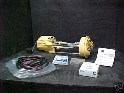
DCJ has a conversion kit to upgrade the '03-'04 systems
If you go with an aftermarket type lift pump, make sure it is flow-thru when failed type, so the CP3 can do it's job.
A Robert Bosch CP3 high-pressure fuel injection pump is used. The pump is attached to the back of the timing gear housing at the left-side front of the engine
DESCRIPTION
The fuel system on the 5.9L Common Rail Diesel Engine uses a rotary mechanical fuel injection pump and an Electronic Control Module (ECM) and is a drive-by-wire system, meaning there is no physical throttle cable.
The fuel delivery system consists of the:
- Accelerator pedal position-sensor module
- Air cleaner housing\element
- Fuel filter\water separator
- Fuel temperature sensor
- Fuel heater
- Fuel rail relief valve
- Fuel rail pressure sensor
- Fuel injection pump
- Fuel injectors
- Fuel tank
- Fuel tank filler\vent tube assembly
- Fuel tank filler-tube cap
- Fuel tank module containing the electric lift pump, roll-over valve and a fuel gauge sending unit (fuel level sensor).
- Fuel tubing\lines\hoses
- High-pressure fuel injector lines
- Low-pressure fuel supply and return lines
- Low-pressure fuel return line
- Overflow valve
- Quantity control Fuel Control Actuator valve
- Quick-connect fittings
- Water sensor\drain module
FUEL INJECTION PUMP
The Cummins 5.9L CRD uses the Bosch CP3 injection pump, used also on the DMax 6.6L V8 CRD and the Jeep 2.8L CRD
DESCRIPTION
A radial, 3-piston pump, with a gear-type supply pump attached to the back, is used as the high-pressure pump for common-rail fuel pressure generation - in this system it is capable of pressures between 300-1600 bar (4351-23206 psi) .
A spring-loaded Cascade Overflow Valve regulates internal housing pressure
Regulated internal housing pressure is oem-specific
The pump shaft is driven by the timing belt at 1:1 ratio to the crankshaft.
Fuel pressure is generated independently of the injection process.
A Fuel Control Actuator solenoid valve regulates injection pressure
The injection pump is lubricated by the pumped Diesel fuel and is not responsible for fuel injection timing.
OPERATION
SUPPLY PUMP
DESCRIPTION
The gear-type supply pump has two functions:
- draws fuel from the fuel supply
- increases fuel pressure for regulation to housing pressure required for internal lubrication and supplying the high-pressure injection pump
OPERATION
This fuel system uses a gear-type supply-pump attached to the rear of the high-pressure pump. This medium-pressure fuel pump is driven by the end of the high-pressure injection pump shaft, and can generate greater than 20" vacuum at the fuel inlet at high rpm.
The supply pump is supplied fuel from the lift pump in the fuel tank through the fuel manager\filter.
The outlet of this pump provides pressurized fuel to a branched circuit internal to the high-pressure pump flange, which supplies both the Fuel Control Actuator solenoid valve and the Cascade Overflow Valve\regulator. Because the pump increases fuel flow and pressure as engine rpm increases, it's output pressure and flow is regulated by the COV.
The COV and supply-pump are not serviced independently of the high-pressure pump.
CASCADE OVERFLOW VALVE
DESCRIPTION
The COV is located on the front cover of the high pressure pump.
The Cascade Overflow Valve has three functions:
- regulation of lubrication fuel to the internal moving parts of the high-pressure pump
- regulation of the fuel pressure being supplied to the Fuel Control Actuator solenoid valve
- return excess fuel to the fuel tank
This regulated internal pressure is known as housing pressure, and is determined by engine displacement and power requirements - the 5.9L CRD requires 5-12.4 bar (80-180 psi)
For comparison, the 2.8L 4-cyl Jeep CRD requires 5bar (73psi)
OPERATION
The COV has a spring-loaded center spool-piece that has a drilled channel with three passages: one for initial low-pressure lubrication, one for lubrication at housing-pressure , and one for overflow. The valve is operated in three stages based on the level of pressure at the inlet.
Stage 1
When the fuel pressure entering the tip of the COV is between 0 and 3 bar (43psi), pressure is too low to overcome regulator spring tension and fuel flows through the center channel, only . This passage always allows fuel flow through to the pump center-ring and lubricates the pump bushings and internal moving parts. This circuit also allows air to bleed during initial cranking and returns the air to the fuel tank.
The COV is in Stage 1 during cranking, only.
Stage 2
When the fuel entering the COV exceeds 5bar (73psi), but is less than 12.4bar (180psi), the spool-piece moves against spring tension aligning a second passage for lubrication purposes.
Stage 2 can be reached during cranking and initial start up.
Stage 3
When fuel pressure exceeds 12.4bar (180psi), the spool-piece aligns with the overflow passage. This stage relieves the pressure into an overflow circuit that sends the fuel back to the inlet side of the gearotor pump, thus limiting maximum fuel pressure to 12.4bar (180psi).
Lubrication fuel continues to flow through all channeled passages during this stage.
Excess fuel is sent back to the fuel tank through the fuel-return circuit
Stage 3 is reached at over-pressure
FUEL CONTROL ACTUATOR
DESCRIPTION
The Fuel Control Actuator solenoid valve is located on the back of the front cover of the high-pressure pump. The solenoid is pulse-width modulated by the ECM and meters the amount of fuel that flows into the high-pressure elements inside the high-pressure pump.
The solenoid is inactive up to 30 seconds after IGNition switch is initially keyed to ON position to allow maximum fuel pressure to the fuel rail during cranking and start up. ECM assumes FCA valve control when CPS signal and rail pressure are within acceptable limits
OPERATION
The Fuel Control Actuator solenoid valve is a pulse-width modulated valve that controls the amount of fuel sent or delayed to the high-pressure pump elements inside the high-pressure pump. The ECM determines the fuel pressure set point based on engine sensor and rail-pressure inputs. If the actual fuel-rail pressure is too low, the ECM commands the solenoid to allow more fuel to flow to the high-pressure pump. This minimizes the difference between the actual fuel-rail pressure reading and the set point. The ECM will also operate the solenoid to delay fuel, reducing flow-rate, if the fuel-rail pressure becomes too high.
The FCA valve is commanded open by the ECM to allow the high-pressure pump to build maximum pressure (1600bar, 23,206psi).
Thus, rail fuel-pressure can be increased or decreased independent of engine speed
High Pressure Pumping Plungers
The FQS valve supplies three high pressure pumping chambers. The pumping chambers have one-way inlet valves that allow fuel to flow into the chambers. The valves then close as the fuel is compressed, causing the high pressure fuel to overcome a spring-loaded ball-and-seat outlet valve.
All three pumping chambers are tied together in one circuit internal to the pump and provide high pressure fuel between 300bar (4351psi) and 1600bar (23,206psi) through a steel line to the fuel rail.
The pump is driven at 1:1 engine speed and is not responsible for injection timing.
Pump function is to provide fuel at high-pressure, while the ECM controls injection pressure and timing.
FUEL RAIL
DESCRIPTION
The fuel rail is mounted to the cylinder-head cover\intake manifold. The rail distributes regulated high-pressure fuel equally to the fuel injectors.
A pressure sensor is screwed into the rail so ECM can read and regulate system pressure.
A pressure solenoid is screwed into the fuel rail to allow regulated overflow return to the fuel tank.
OPERATION
The fuel rail stores the fuel for the injectors at high pressure. At the same time, the pressure oscillations which are generated due to the high-pressure pump delivery and the injection of fuel are dampened by rail volume.
The fuel rail is common to all cylinders, hence it’s name "common rail". Even when large quantities of fuel are extracted, the fuel rail maintains a constant inner pressure. This ensures that injection pressure remains constant from the instant the injector opens to the end of the injection event.
FUEL LINES
DESCRIPTION
LOW-PRESSURE FUEL LINES
All fuel lines up to the fuel injection pump are considered low-pressure. This includes the fuel lines from the fuel tank module to the inlet of the high-pressure fuel injection pump. The fuel-return lines and the fuel-drain lines are also considered low-pressure lines.
High-pressure lines are used between the fuel injection pump and the fuel injectors
HIGH PRESSURE FUEL LINES
High-pressure fuel lines are used between the high pressure fuel injection pump and the fuel rail, and between the fuel rail and fuel injectors
All other fuel lines are considered low-pressure lines.
OPERATION - HIGH PRESSURE FUEL LINES
High-pressure fuel lines deliver fuel under extremely high pressure - between 300-1600 bar (4351-23206 psi) - from the high-pressure pump to the rail to the fuel injectors. The lines expand and contract from the high-pressure fuel pulses generated during the injection process, which can delay the injection event - ECM compensates for that based on component specs
All high-pressure fuel lines between the rail and the injectors are of the same length and inside diameter to ensure equal-duration injection events, cylinder to cylinder.
Correct high-pressure fuel line usage and installation is critical to smooth engine operation.
FUEL MANAGER\FILTER
FUEL FILTER / WATER SEPARATOR
DESCRIPTION
The fuel filter/water separator assembly is located on the left rear side of the engine. It incorporates the fuel temperature sensor, fuel heater and a Water-In-Fuel (WIF) sensor.
Only the fuel filter cannister and the WIF sensor are serviced separately. The top-loaded fuel filter has a 3-micron element and the cap tightens clockwise to the housing.
OPERATION
The fuel filter/water separator protects the high pressure fuel injection pump by removing water and contaminants from the fuel with a 3-micron filter element. The construction of the filter/separator allows fuel to pass through it, but helps prevent moisture (water) from doing so. Moisture collects at the bottom of the cannister for draining.
A Water-In-Fuel (WIF) sensor is attached to the fuel filter cannister and is serviced separately.
The fuel heater is in a thermoplastic module inside the fuel manager head - it is not serviced separately from the head.
WATER IN FUEL SENSOR
DESCRIPTION
The WIF sensor is attached to the bottom of the fuel filter/water separator cannister. The sensor also has a drain channel and provision for adapting a drain hose.
OPERATION
The sensor varies an input to the ECM, allowing it to sense water in the fuel filter/water separator.
As the water content in the filter/separator increases, the resistance across the WIF sensor decreases. This decrease in resistance is measured by the ECM and compared to a calibrated standard value. If the resistance drops to a value between 30 and 40 kohms, the ECM will activate the Water-In-Fuel warning lamp. This all occurs when the IGNition key is initially switched to ON position
FUEL HEATER
DESCRIPTION
The fuel heater is used to prevent diesel fuel from waxing and plugging the fuel filter during cold weather operation.
The fuel heater is located in the fuel heater module, next to the fuel temperature sensor - the module is internal to the fuel manager head.
On temperature is 7°C (45° F), off temperature is 29°C (85° F).
OPERATION
The element inside the heater assembly is made of a Positive Temperature Coefficient (PTC) material, and has power applied to it by the fuel heater relay anytime the ignition key is in the ON position. PTC material has a high resistance to current flow when its temperature is high, which means that it will not generate heat when the temperature is above a certain value. When the temperature is below 7°C (45° F), the resistance of the PTC element
is lowered, and allows current to flow through the fuel heater element warming the fuel. When the temperature is above 29°C (85° F), the PTC element’s resistance rises, and current flow through the heater element stops .
Fused voltage to operate the fuel heater is supplied from the Ign switch, through the fuel heater relay, when the ECM senses the IGNition (key) switch is ON.
Sensed temperature for on and off operation is the temperature of the element, which allows full heating only when the temperature drops below 7°C (45° F) - element should not produce full heat on an 18.3°C (65° F) day, for example
ELECTRIC FUEL LIFT PUMP
ELECTRIC LIFT PUMP
The '03-'04 trucks have a Carter sliding-vane type lift pump attached to the Fleetguard fuel manager head on the engine supplying ~15psi - pressure is regulated via internal bypass
The '05^ trucks have a rotary-vane type in-tank lift pump in the fuel tank module, supplying ~9psi - pressure is regulated via external bypass, returning excess fuel to the tank
DESCRIPTION
The under-hood Fuse Center contains a fuse and solid-state relay for an electric lift pump.
Relayed power is supplied to the pump, which is mounted in the fuel tank
The lift pump supplies 9psi @50gph @ 5amps
OPERATION
Fused power to the solid-state relay is supplied when the IGN switch is in the ON position.
ECM controls the relay in two modes, prime and run - a safety feature helps prevent fire in event of accident or other emergency
At power-ON, during WTS, ECM closes the solid-state relay for 2 seconds to prime the low-pressure fuel system to the Inj Pump - if ECM does not sense pulses from the Crank Position Sensor within 25 seconds or when intake air heater shuts off, the relay is powered down - relay is powered up again when CPS senses crankshaft rotation, indicating START in progress
Power is maintained until crankshaft stops, which is a saftey feature, or when IGN is switched OFF
The CP3 Inj Pump has a built-in gearotor-style lift pump, driven by the pump shaft - it will develop 20" vacuum at higer rpm, and is designed to pull fuel from the tank thru a filter.
The '03-'04 Dodge trucks have an additional Carter-style rotary lift pump mounted on the fuel manager head - those are not flow-thru when fail type, so the CP3 cannot pull fuel from the tank as the electric pump fails - this will leave you on the side of the road, even tho the CP3 could get you home
The '05-up trucks have an in-tank electric lift pump that runs at a constant 9psi - it flashes toward 30psi at key-on, then settles back to 9psi as the CP3 bypass begins to function - it is a rotary-vane type externally bypassed flow-thru when fail pump, designed to run in Diesel fuel, so the CP3 can draw fuel from the tank if the electric pump fails - this setup will not leave you stranded on the road, dead.
DCJ has a conversion kit to upgrade the '03-'04 systems
If you go with an aftermarket type lift pump, make sure it is flow-thru when failed type, so the CP3 can do it's job.
Last edited: