• Welcome to The Truck Stop! We see you haven't REGISTERED yet.

    Your truck knowledge is missing!
    • Registration is FREE , all we need is your birthday and email. (We don't share ANY data with ANYONE)
    • We have tons of knowledge here for your diesel truck!
    • Post your own topics and reply to existing threads to help others out!
    • NO ADS! The site is fully functional and ad free!
    CLICK HERE TO REGISTER!

    Problems registering? Click here to contact us!

    Already registered, but need a PASSWORD RESET? CLICK HERE TO RESET YOUR PASSWORD!

Code Scanner won't communicate with 99 Suburban

Paveltolz

Доверяй, но проверяй
Messages
3,063
Reaction score
2,862
Location
Saratoga Springs, UT
The scanner is an INNOVA unit with OBD1 and II connectivity (different cables etc.) it works as advertised in the 96 Silverado, 97 Accura and both 2017 VW Golfs.

I've swapped computers from the Burb to the Silverado and the Burb box talks to the scanner while in the Silverado. However, the Silverado's computer doesn't connect when installed in the Burb.

I've run through the GM Repair manual checklists for troubleshooting realizing I have to check a couple of lists for different issues because the manual was written for Tech 2 scanner abnormalities. "CKT 800, no commo on the UART Data Line" or "CKT 1870 No Commo on Class-2 Data Line." Assuming that one of these is creating the issue and that the manuals for this don't change between 1997 and 1999 as I don't have the 99 manuals yet (next Wednesday).

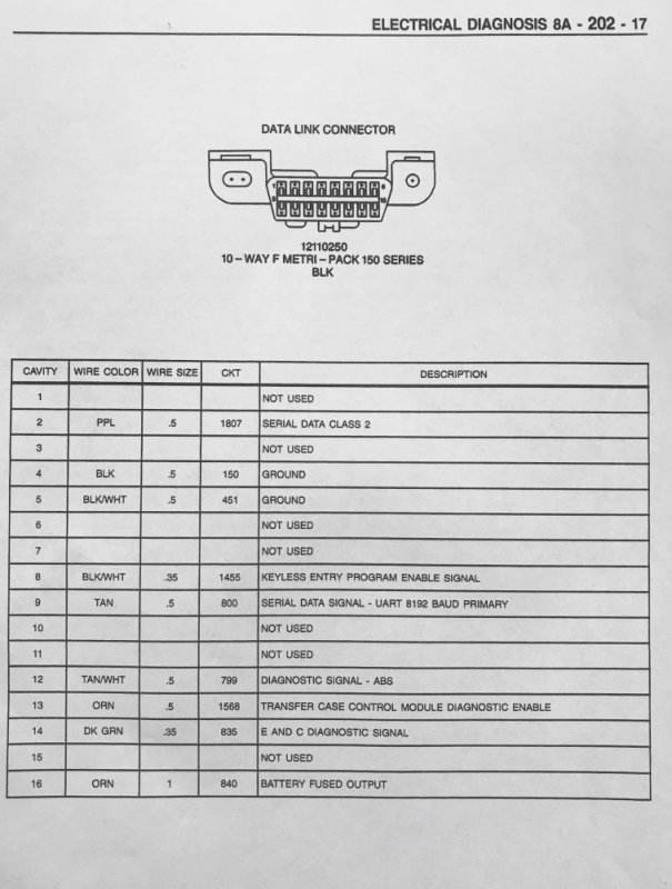
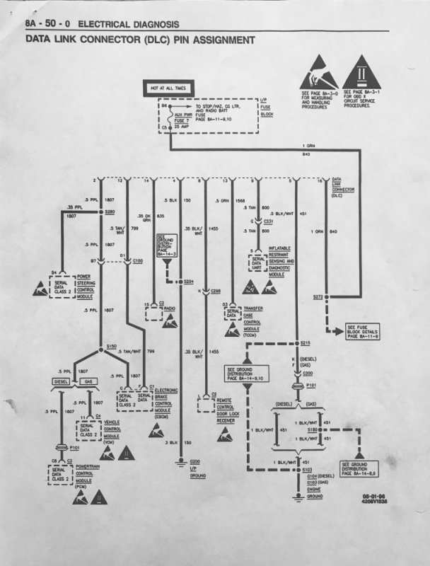
At the git go, "If the Powertrain Control Module (PCM or "Computer") is not accessible with a scan tool, check for an open in Purple (PPL) (1807) wire." Test Result: Connectivity is good between the Data Link Connector (DLC) pin 2 and the PCM's #3 connector at its C8 Pin out.

I've gone through the other circuits doing the various tests for grounds, connectivity, voltages, ohms etc at the specified pin outs and components and the only abnormality noted so far is there is too much voltage at both the purple wire (2.4 VDC) at connector 2 (top row, second from the left) as well as the Tan wire (4.5 VDC) at connector 9 (bottom row, 1st one on the left). "Greater than 1 VDC = repair the wire." I've done the same circuit tests on the Silverado and the voltages are all below 1VDC.

So, where the heck is the 'extra' power coming from and what does "BPMV" mean (Bullet for My Valentine/Vehicle...Burglary From Motor Vehicle...Break Pressure Modulator Valve)? One of the splices for the PPL wire is located on the 'Engine Harness approx. 13 cm into [the] BPMV Breakout." I'll keep looking in the manuals to see what I can find but, this should be enough for one post but, will the Trouble Shooting checklists help?
IMG_0110.jpg IMG_0112.jpg
 
If it works in another vehicle and a known good one won't work in it, then you know the problem is in the vehicle. I would start by finding out if yours has a bus bar for the obd2 system. I know newer vehicles have a bus bar in the drivers side kick panel where all the obd2 data wires connect together so you can isolate them one by one. My guess is you have either a module on the obd2 data bus shorting, or a short in one of the obd2 data wires. All you can do is isolate them to just 1 or 2 modules and make sure the bus works(can connect a scanner and communicate), then reconnect them 1 at a time until you find the one that shuts it down.
 
If it works in another vehicle and a known good one won't work in it, then you know the problem is in the vehicle. I would start by finding out if yours has a bus bar for the obd2 system. I know newer vehicles have a bus bar in the drivers side kick panel where all the obd2 data wires connect together so you can isolate them one by one. My guess is you have either a module on the obd2 data bus shorting, or a short in one of the obd2 data wires. All you can do is isolate them to just 1 or 2 modules and make sure the bus works(can connect a scanner and communicate), then reconnect them 1 at a time until you find the one that shuts it down.
Thanks Ferm, much appreciated. I've not located the possible bus bar yet and there's enough that I'm finding different between the 1997 manuals and the actual 1999 vehicle that I'm going to shelve the issue for now and once the 1999 manuals show up, start the research again. Right now I'm finding that I'm chasing things that don't exist on this Burb so results are suspect.
Fuses are all good though as are the grounds....
 
Are you referencing the "ground" in the connector pin 4 or 5 or 'just any chassis ground point'? It makes a difference esp. if there is an issue with a ground the connector grounds use. For example I found a "hack" 2' from the ECM ground on a 1992 S-10 and a scotch lock 6" from that making the 2 grounds into 1 wire. Corroded with enough resistance the ECM wouldn't go into diagnostic mode. Measuring the connector voltages referencing ground via the bolt in the doorframe had everything fine and cost 1/2 day, but later, referencing the connector ground showed major voltage problems. Ran ok otherwise - just no code readout.

Any module that doesn't have a good ground can float all it's pins high looking for a path to ground. ABS modules come to mind and have bulletins for bad grounds on newer stuff.
Yes to referencing the 'Ground' to pin 4, not to pin 5. I'll give the voltage checks against a chassis ground a look. I just wish I could figure out where the the commonality is between the two circuits is that they are getting the additional voltage and at different amounts but, it's most likely in the looming where they run out from the DLC. I'll find it, eventually.

You do know there are two (2) different sets of manuals old/new for 1999 C/K right
Yes and how to tell the difference in trucks vs. manuals?
Mine, having an 'older' style HVAC (no cabin filter etc.) and other stuff that looks different from the plethora of 1999 GM Youtube Videos is probably the old one. My luck will result in a set of "new" manuals arriving..."life, be in it."

Pictures (and GIFs) being worth a thousand words, and my not having the picture, I sometimes feel like the 'Ruby Rodd' character from Fifth Element, standing in the Temple and holding the seemingly nonfunctional stone and saying to himself, 'Why to I always get the broken one?"
 
Last edited:
Yes and how to tell the difference in trucks vs. manuals?
Mine, having an 'older' style HVAC (no cabin filter etc.) and other stuff that looks different from the plethora of 1999 GM Youtube Videos is probably the old one. My luck will result in a set of "new" manuals arriving..."life, be in it."
Old is GMT400 "blue shop manuals next gen 1999 C/K are "grey."
 
I have a set of 98 if it will help Paul

Thanks Brother. It would help if you would simply look in the Electrical Diagnosis portion for the Data Link Connector and let me know what the minimum Voltage Output at Pin 2 and Pin 9 is listed as. in the 97 manuals I have, the DLC part starts at section 8A-50 with the trouble shooting CKT-800 (pin 9) on page 8A-50-3 and CKT-1870 (Pin 2) on page 8A-50-4.
Mine say 'less than 1 VDC' or go fix the respective wire.

Again, thank you.
 
The manuals showed up today which is a day early and for that I'm grateful. In the preliminary reading on the DLC issues, it appears that the voltages at those pins is correct ('no more than 5 VDC Signal') and, from what I can tell, all indicators are pointing to the Passlock module. The PCM has been programed so Passlock shouldn't be an issue but, and its a big BUT, the Previous owner has done some interesting things to this vehicle and I can see at least one multi pin connector behind the instrument panel/kick panel IVO the steering column that is disconnected. There's no door chime, seatbelt buzzer or lights on warnings and the 'speaker' is still plugged in to the convenience center so maybe, just maybe there's a relation and something to take a closer look at. Hope springs eternal.
 
Heads up, on my 99 there was a harness issue at the PCM in that the harness that came into the cabin via the drivers side was exposed in the passenger foot well so when any passenger would stretch out by putting their feet high up into the foot well they would be pushing on the harness with time this will pull pins out of the PCM been there done that.

I fixed the issue by pushing (non-conductive tool) all the pulled pins back into place with harness while it was attached to PCM fastening the harness up high and making sure it would not move if someone pushed on it while stretching out.
Thank you, I will definitely pull that connector and inspect the wiring terminals and how they look as apposed to the others, specifically at the C8 pin where the suspected purple wire resides. When I did the continuity check between that pin and the #2 port on the Data Link Connector, I probed the back side of the terminals instead of at the harness face. It was a "Rube Goldberg" balancing act trying getting the probes to maintain contact at both ends of the circuit as it was so I didn't go at the PCM side from the front.
 
Thank you, I will definitely pull that connector and inspect the wiring terminals and how they look as apposed to the others, specifically at the C8 pin where the suspected purple wire resides. When I did the continuity check between that pin and the #2 port on the Data Link Connector, I probed the back side of the terminals instead of at the harness face. It was a "Rube Goldberg" balancing act trying getting the probes to maintain contact at both ends of the circuit as it was so I didn't go at the PCM side from the front.
Good luck there..
 
Back
Top